Methods for determining the cross-section of copper wire for furniture lighting
to determining the cross-section of a copper wire , depending on the type of power supply to the circuit: electronic or induction.
Calculation of wire cross-section for an electronic unit
For an electronic power supply, the permissible length of wires in the secondary circuit is no more than 2 m. In this case, use a wire with a cross-section specified in the documentation for the transformer or refer to the table below. The total power is the sum of the powers of the lamps in the wardrobe lighting circuit.
Table of cross-sections of copper wires in a 12 V lighting circuit up to 2 meters long (for electronic power supplies)
| Total load power, W | Wire cross-section, mm2, not less |
| 60 | 0,75 |
| 100 | 1,5 |
| 150 | 2,5 |
| 200 | 3,0 |
| 250 | 3,8 |
| 300 | 4,5 |
| 400 | 5,8 |
Watch the video of calculating the cross-section and length of the wire for illumination with LED strip
Calculation of wire cross-section for an induction transformer
For an induction transformer, the length of the wire is limited only by the voltage drop across the wires. That is, the length of the wire can be significantly greater than for electronic (pulse) units, subject to compensation by increasing the cross-section of the wire.
Below is a table for selecting the wire cross-section depending on the total power of the lamps connected to the induction transformer and the length of the wires.
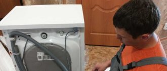
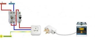
Please tell me the most competent solution in this situation. There is a box under the ceiling that holds a 220V power cable. The cable, in my opinion, is 2x0.75. From the same box there are two similar cables to the ceiling niches. One for niche No. 1, the second under the ceiling is soldered into niches No. 2 and No. 3. The length of these cables from the box to the niches is approximately 5-7 meters. I want to connect an LED strip with a power of about 10W per meter into these niches. Length of tape in niches: No. 1 – 6 m No. 2 – 6 m No. 3 – 3 m The question is this. Is it better to connect one step-down transformer from 220 to 12 volts in a box and connect cables from it to a niche, or is it better to solder the 220-volt wiring in the box and connect individual power supplies to each niche?
The cable in the 220V circuit must be 3x1.5 mm (group line) The cable in the 12V circuit must be even thicker.
R_V wrote: The question is this. Is it better to connect one step-down transformer from 220 to 12 volts in a box and connect cables from it to a niche, or is it better to solder the 220-volt wiring in the box and connect individual power supplies to each niche?
Better individual blocks for each niche. In 12 V circuits, voltage losses are high, so the length of low-voltage lines must be reduced as much as possible. And ksiman is right. Moreover, 0.75 is hardly a cable. Most likely a cord not intended for wiring at all.
Dear ksiman and Dale, your arguments are clear to me, and if I were to install the wiring now, I would make it with a cross-section of 1.5 or even 2.5 in order to put one 200W power supply in a box and distribute it to all 3 niches. But I have what I have. The repairmen laid a cable to all the niches, in my opinion not even 2x0.75, but 2x0.5. The question is, is it possible to connect under existing conditions? I already realized that I will definitely have to install separate power supplies for each niche, because... 12V over a 2x0.5 square cable at a distance of 5 meters is not realistic. But for 220V and the total total power of the tapes is 180W - in my opinion, it is quite acceptable. Or I'm wrong? The total current is 9.5-10A, but if I understand correctly, this is the current from the power supply when switching to 12V, and the current to the power supply is less. How to determine which one?
Read also: Pressure testing of high pressure cylinders
Can anyone give me some advice? If after the power supply of the LED strip, which reduces the current from 220 to 12 volts, there is a current strength of about 10 Amps, then what is the current strength before the power supply in the 220 Volt cable? The power consumption of the tape is about 180W.
You can do it wrong in many ways, but these questions are not here. Group fixed wiring is not made thinner than 1.5 kV
R_V wrote: 12 volts carries a current strength of about 10 Amps, then what is the current strength to the power supply in the 220 Volt cable? The power consumption of the tape is about 180W.
R_V wrote: for 220V and the total total power of the tapes is 180W - in my opinion, it is quite acceptable. Or I'm wrong?
what if suddenly something shortens? The machine won't even feel it - you'll burn out. Therefore, for stationary wiring of any power, 1.5 mm2 of copper is required under the protection of a circuit breaker of no more than 10 A
I understand why you can’t put 180W 12V on such a wire with their current strength, but I don’t understand why you can’t use 220V for the same power. Today I saw a sign in the store that said that a cross section of 0.5 can be used up to 300W (or something like that).
R_V wrote: I understand why you can’t put 180W 12V on such a wire with their current strength, but I don’t understand why you can’t use 220V for the same power. Today I saw a sign in the store that said that a cross section of 0.5 can be used up to 300W (or something like that).
Section 0.5 cannot be used. Forbidden. Judging by the fact that the answer “prohibited by the PUE” does not suit you, I will try to explain it to you in a simple way. A thin wire is a wire with increased resistance. Therefore, the lighting line will have increased resistance. And let’s assume that the circuit breaker for lighting is 16 A. So, for this machine to ever turn off, you need a current of at least 23 A. That is, if the line resistance (total resistance, including the shield, the entrance riser, the cable line to the transformer and the winding resistance) is 10 Ohms. – your machine will never turn off in the event of a short circuit. That is, this wiring will quietly burn behind the ceiling. And you will breathe combustion products. And another argument - these wires are simply not intended for wiring. Their purpose is to connect table lamps.
LED lighting under cabinets in the kitchen is ergonomic, beautiful and modern. In the article we will talk about how to choose the right system elements, what connection schemes are available, how to install the tape as an independent element and in a special box (profile).
Choosing an LED strip for lighting under cabinets is an interesting, effective and not too complicated solution for the home craftsman. Such additional lighting undoubtedly also fulfills aesthetic purposes - it highlights individual functional areas, accentuates decorative elements with color, and sets a fashionable, modern tone for the kitchen design.
Conclusion on choosing the wire cross-section for constant voltage:
The shorter and thicker the wire through which direct current flows, the lower the voltage drop across it, the better . That is, the voltage loss in the wires is minimal.
If you look at Table 2, you need to select the values from the top-right, without going into the “blue” zone.
For alternating current the situation is the same, but the issue is not so acute - there power is transferred by increasing the voltage and decreasing the current. See formula (1).
In conclusion, here is a table in which the DC voltage drop is set to a limit of 2%, and the supply voltage is 12 V. The required parameter is the maximum wire length.
Attention! This refers to a two-wire line, for example a cable containing 2 wires. That is, the case when, through a cable 1 m long, the current makes a path of 2 m, back and forth. I brought this option because... it is most often encountered in practice. For one wire, to find out the voltage drop across it, you need to multiply the number inside the table by 2. Thanks to attentive readers!
Table 3. Maximum wire length for 2% DC voltage drop.
According to this table, our one and a half rack can only be 1 meter long. It will drop 2%, or 0.24V. We check using formula (4) - everything agrees.
If the voltage is higher (for example, 24 V DC), then the length can be correspondingly longer (2 times).
All of the above applies not only to constant voltage, but also to low voltage in general. And when choosing a cross-sectional area in such cases, one should be guided not only by the heating of the wire, but also by the voltage drop across it. For example, when powering halogen lamps through a step-down transformer.
Please comment on the article, how does theory coincide with practice?
Source
Selecting LED strip
An important characteristic of LED strips for installation under cabinets in the kitchen is resistance to water vapor. Insufficient moisture protection can lead to a short circuit, and, therefore, to the risk of fire. When purchasing a tape, you need to pay attention to the degree of protection of the shell, which is marked with a two-digit number after the Latin letters IP. The first number indicates protection from dust and dirt, and mechanical damage. The second number is protection against moisture. The security of a device or device is assessed on a scale from 0 to 9 for both parameters.
In terms of tightness (moisture and dust resistance), LED lamps and strips can be marked:
- IP33 - open type of conductor, not recommended for kitchens;
- IP65 - one-sided sealing of the side on which electronic elements are located, allowed for installation in a humid kitchen environment;
- IP67, IP68 - double-sided, completely sealed tape - recommended for installation in the kitchen.
If the selected lamp or strip with LEDs has insufficient security, it is necessary to use a protective shade or special profiles to collectively ensure the proper level of security.
In order for the LED strip to provide enough light, it is important to choose the right power density, which is characterized by the number of LEDs per linear meter. Each type of strip can have a different number of LEDs. This can be determined both visually and by reading the characteristics of the product.
For decorative purposes, 30 or 60 LEDs per meter are usually sufficient. To fully illuminate the work surface, it is better to choose a strip with 120 or 240 diodes.
When calculating the illumination, you need to take into account the power consumed by the tape, remembering that compared to incandescent lamps, the luminous flux of LEDs is approximately 5 times higher.
Read also: Mold for pouring metal
Table. Belt power calculation
| Video.1. Calculation of the cross-section and length of the wire for LED strip lighting |
| LED type | Number of diodes, pcs./1 linear m | Power consumption, W/1 linear m |
| SMD-3528 | 60 | 4,8 |
| SMD-3528 | 120 | 9,6 |
| SMD-3528 | 240 | 19,2 |
| SMD-5050 | 30 | 7,2 |
| SMD-5050 | 60 | 15 |
| SMD-5050 | 120 | 25 |
The numbers in the strip markings indicate the size of one LED:
- SMD-3528 - diodes measuring 3.5x2.8 mm;
- SMD-5050 - diodes measuring 5.0x5.0 mm.
For monochrome strips with the specified characteristics, the luminous flux, measured in lumens and which is another characteristic of LEDs, will be maximum. For polychrome RGB tapes, the color of which is set depending on the settings of the regulator or control controller, the total number of crystals in each diode corresponds to a combination of basic colors that do not turn on simultaneously. Consequently, when only part of the crystals that produce a certain color are working, the luminous flux will be lower.
The colors of monochrome diodes with their own crystal glow are:
The color of monochrome diodes is characterized by a narrow spectrum of emission, which should be taken into account when choosing a backlight. The color of objects and, most importantly, products is significantly distorted; they may not look the same as under natural light or illuminated by fluorescent lamps.
The white monochrome LED is an ultraviolet-emitting semiconductor coated with a phosphor. The principle of operation is similar to fluorescent lamps that are familiar to most. The shade can also be from “warm” to “cold” and is indicated in the form of the corresponding glow temperature, measured in Kelvin as with conventional LED lamps.
The color of the surface of the printed circuit board on which the LEDs are located is usually white, but you can choose other colors: brown, yellow, black, which will look better on furniture when installed openly. For ease of installation, the tape is equipped with adhesive tape on the reverse side.
Selecting a power supply and additional devices
You cannot plug the LED strip into a household outlet - it will burn out immediately. It is designed to operate at direct current with a voltage of 24 or 12 V, obtained through an appropriate pulse converter (power supply). The power of the device must correspond to the total power consumption of all connected tapes. For example, you need to connect three 5 m SMD-5050 reels with a power of 7.2 W/linear. m. The total capacity is:
5 m 7.2 W/linear m = 36 W
The power supply is selected with a margin of 20%, therefore, you will need a device with a power of at least 45 W.
The design of the block can be different:
- Sealed, compact unit in a plastic case.
- Sealed power supply in an aluminum case. Expensive, climate-resistant, often used in outdoor, street lighting.
- Open block in a perforated housing. The largest, inexpensive, requires additional protection from direct moisture. There are powerful models - one block is enough for all the illumination.
- Network power supply. Low power, up to 60 W, does not require installation. Multiple tapes will require separate power supplies.
The kitchen power supply must be moisture-resistant or installed in a place protected from moisture. It is desirable that the driver contains protection against voltage surges, which extends the life of the LEDs.
It is not recommended to connect LED strips in series, otherwise wear will be high and luminosity will be uneven. When connecting several tapes, it is correct to use an amplifier that provides uniform current supply to different sections of the electrical circuit.
If desired, the backlight can be connected via a dimmer - a device that smoothly reduces the power and luminosity of lighting fixtures. This way you can maintain the backlight in the “work” and “rest” modes.
To control the LED strip, PWM controllers are used that can provide the correct shape of the pulsating current to adjust the brightness of the LEDs
Amplifiers and dimmers are matched to the lighting system based on current strength.
Examples to understand the situation
For example, let's take an ordinary 50 W halogen lamp, which is powered by a voltage of 220 V through the primary circuit of the transformer, and the same powered by 12 V through the secondary circuit. Let's compare the current that flows through the wiring connected to these two lamps.
- 50/220=0.23 A.
- 50/12=4.2 A.
Imagine what a difference it makes. But a current strength of more than 4 A is a large value. Of course, a lot will depend on the transformer itself, or, more precisely, on its power. One example can be given that will show the incompetence of home craftsmen.
For example, for halogen lighting a 1 kW transformer is used. Let's make a reservation - this is for example. So, inserting this quantity into the formula of Ohm’s law, we get:
1000/12 = 83 A. Such a current can withstand a wire of 16 mm², and certainly not 1.5 or 2.5. By the way, this is the size of a copper cable. That is, it turns out that the correct choice of wire cross-section affects the quality of the entire electrical wiring. But that's not all.
As for powerful transformers for a low current of 12 V. By the way, a power of 200 W is already a big indicator. So it is necessary to note that the brightness of the lighting has nothing to do with the power supplied to the lamps. That is, there is a connection, but it revolves around the resistance of the lamps and wires. And the higher the resistance, the brighter the lighting decreases. And the resistance itself depends on the length of the laid wiring and its cross-section. And if the length to the resistance is in direct proportion. That is, the further the lamp is installed from the transformer, the lower the brightness of the glow. It is inversely related to the cross section. The higher this indicator, the less resistance, the brighter the lamp burns.
What does this mean?
- Firstly, taking wires for low current, so to speak, whichever ones you come across, is a wrong and disastrous decision.
- Secondly, by comparing all the characteristics of electrical devices (in this case, lamps), you can assemble a circuit that will work efficiently and for a long time, without creating unnecessary problems.
- Thirdly, it is necessary to correctly select groups of lamps, taking into account the cross-sections of cables suitable both for the group and for each individual lighting fixture.
LED backlight connection diagrams
Basic rules for connecting lighting elements into a circuit and installation:
- observe polarity;
- power it through a power supply with a voltage of 12 or 24 V in accordance with the type of tape and marking, placing it as close as possible to the tape (maximum distance - 10 m);
- The tape should not be sharply bent or twisted. It is better to cut and make the corner by soldering (with care, then insulating the conductive paths with heat-shrink tubing) or with a special connector. Soldering, according to craftsmen, ensures contact without electrical losses;
- the fewer connections and the thicker the wire cross-section, the less electrical current loss;
- It is better to mount a high-power tape in a profile (box);
- pieces of tape longer than 5 m should only be connected in parallel;
- Place the power supply in a ventilated place, protecting it from overheating.
The places where the LED strip can be cut are usually shown on the product itself.
Below are the basic connection diagrams for monochrome and RGB strips.
Direct connection diagram for LED strip. Several tapes are connected in parallel to one current source
Connecting an LED strip using a dimmer to adjust brightness
Several LED strips, switched on using a dimmer or PWM controller, must be connected using an amplifier
Connection diagram for RGB LED strips
RGB strips are connected to the controller with four wires, three of which are responsible for one of the colors, the fourth is common. Marking: R - red, G - green, B - blue. The “V-plus” wire is common. The easiest way to connect is using a connector, but you can also carefully solder it. To independently connect the controller and amplifier, two power supplies are sometimes used in the connection diagram.
Read also: How to choose a thermal head for a heating radiator
How to choose a wire cross-section for connecting a 12V tape
LED strip is very popular when creating decorative lighting in the interior, and is also widely used by professionals in the advertising and design business.
Important! The cable cross-section depends on the current passing through it.
Let's use Table 1 and get the result that for this example the required wire cross-section is S = 0.5 mm². Let's check this value taking into account the voltage loss in the cable.
Address
Russia, Barnaul
- home
- For landlords
- Delivery
- Basket
- Catalog
- Back office login
- Communication with the administration
Fill out the form and our specialists will contact you shortly.
Tools and materials for installing LED strips
To install the LED strip under kitchen cabinets yourself, you will need:
- the connection of elements can be done in various ways, and you will need: a soldering iron, solder, rosin and heat-shrinkable tubing, or wire lugs and crimp for lugs, or connectors;
- scissors;
- insulating tape, double-sided tape, fasteners;
- a tool for cutting holes in furniture for laying wires, for example a jigsaw;
- selected LED strips;
- power supply and other elements of the electrical circuit, if necessary - dimmer, amplifiers, controller;
- box (profile) - when performing the appropriate installation;
- cable.
It is important to understand that LEDs still produce heat when they glow. It is directed into the substrate, the base of the diode. To prevent overheating of semiconductors, which significantly reduces their service life, it is advisable to glue the tape to a special aluminum profile or substrate with high thermal conductivity.
Calculation of wire cross-section at a voltage of 12 volts
The use of low-voltage lighting systems, when the luminaires are powered by a reduced voltage through a transformer, is currently quite widely used.
This growing popularity is primarily due to the high degree of electrical safety of such lighting systems; voltage 12 V is considered to be conditionally safe, which allows the use of low-voltage lighting systems in rooms with a high or increased degree of danger.
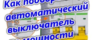
Selection of cable cross-section
As a rule, to install lighting in the kitchen, a cable with a cross section of 0.5-2.5 mm 2 is used.
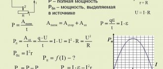
The cable cross-section can be accurately calculated using the formula:
- I - current, I = P/U or I = U/R (P - power, U - voltage, R - resistance);
- ρ - resistivity, for copper cable ρ = 0.0175 Ohm mm 2 /m;
- L—cable length;
- ΔU is the maximum permissible voltage drop between the power supply unit (PSU) and the load (tapes), ΔU = UBP–UΣtape, if the voltage of the PSU is 12 V and the tapes are 12 V, then ΔU is taken to be 5–10%, i.e. 0 .6–1.2 V.
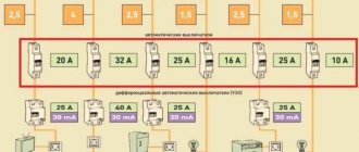
The cross-section of the cable also depends on the length of the wiring; the longer the wire, the less power will be supplied to the light source, as can be seen from the following table:
| Wire length, m | Power released at the load, W | |||
| Wire size | ||||
| 1.5 mm 2 | 2.5 mm 2 | 4 mm 2 | 6 mm 2 | |
| 50,0 | 50,0 | 50,0 | 50 | |
| 2 | 45,5 | 47,2 | 48,2 | 48,8 |
| 4 | 41,5 | 44,6 | 46,5 | 47,7 |
| 6 | 38,1 | 42,3 | 44,9 | 46,5 |
| 8 | 35,0 | 40,1 | 43,4 | 45,5 |
| 10 | 32,4 | 38,1 | 42,0 | 44,4 |
Calculation of voltage drop on a wire for direct current
Now, using formula (2), we calculate the voltage drop on the wire:
U = ((ρ l) / S) I, (4)
That is, this is the voltage that will drop on a wire of a given cross-section and length at a certain current.
These are the tabular data for a length of 1 m and a current of 1A:
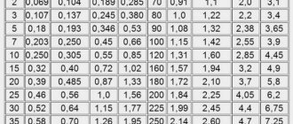
Table 1. Voltage drop on a 1 m copper wire of different cross-sections and a current of 1A:
| S, mm² | 0,5 | 0,75 | 1 | 1,5 | 2,5 | 4 | 6 | 8 | 10 |
| U, B | 0,0350 | 0,0233 | 0,0175 | 0,0117 | 0,0070 | 0,0044 | 0,0029 | 0,0022 | 0,0018 |
This table is not very informative; it is more convenient to know the voltage drop for different currents and cross sections. Let me remind you that calculations for choosing the wire cross-section for direct current are carried out according to formula (4).
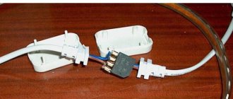
Table 2. Voltage drop for different wire cross-sections (top row) and current (left column). Length = 1 meter
What explanations can be made for this table?
1. in red those cases when the wire will overheat, that is, the current will be higher than the maximum permissible for a given cross-section. I used the table given on SamElektrika: Selecting the cross-sectional area of the wire.
2. Blue color - when the use of too thick wire is economically and technically impractical and expensive. The threshold was taken to be a drop of less than 1 V over a length of 100 m.
Installation of LED strip under kitchen cabinets
The basis of a well-executed installation is thoughtful planning - how to choose where and what elements of the circuit to place.
The LED produces a directed beam of light, most often it is a 120° sector strictly along the central axis of the semiconductor. Less common options are 90°, 60° and 30°. By attaching the tape to the bottom of the hanging cabinet and moving away from the wall, a very clear stripe is formed on the vertical surface, moreover, wavy between light and shadow, which can have a detrimental effect on the overall picture.
It is necessary to distribute the light source so that the dividing strip of light and shadow from the backlight falls on a natural boundary, for example, between the edging of the working surface and the wall cladding. In the simplest case, the tape is mounted close to the wall to illuminate it completely. By choosing different options, you can work with the visual “depth” of the working surface to the benefit of the overall design.
Strips with diodes that have a narrow sector of illumination can be mounted at the very edge under the cabinet so that the wall is not illuminated at all. A universal way to distribute light is to use aluminum profiles with light-diffusing protective films. Even with the height of the profile sides, if desired, you can form the required shape of the illumination spot.
The installation itself, with some skill in working with the tool, is not very difficult.
- We pass the cable to the connection point as inconspicuously as possible by drilling a small diameter hole on the back of the cabinet.
- A low-power LED strip can be attached directly to the prepared and grease-free surface of the bottom of kitchen cabinets. Tapes of measured length, having an adhesive layer, are simply applied to the selected location and pressed, removing the protective film immediately before installation. If there is no such layer, you will need double-sided tape. To disguise the tape, you can protect it with a profile to match the cabinet.
- We fix the power supply, make electrical wiring, carefully securing the wires using clips or double-sided tape.
- We connect all the elements into a circuit, be sure to check the wiring with a tester for a short circuit between the supply wires, and only then connect it to the network. The backlight is ready.
If, due to increased power or for aesthetic reasons, you plan to install the strip in a profile, then first it is easier to lay the LED strip in the profile and connect the power pins. After this, the profile is secured to the cabinets using double-sided tape. You will have to change the sequence only if the profile is attached using self-tapping screws screwed in from its inside side.
In the next video, the same master as in the previous video gives advice on installing the tape in the box.
Main conclusions
Selecting a cable for an LED strip is an important and necessary procedure. It allows you to improve the glow mode of the tape and extend the service life of the backlight. The correct choice of cable is made according to the following criteria:
- current consumption;
- voltage drop;
- installation and connection conditions.
Calculating the cable cross-section is not difficult, but there is an easier way. You need to find one of the online calculators on the Internet and use it for quick and accurate calculations.
Explain your methods for determining the cable parameters for an LED strip in the comments.