The conversion of electrical energy into kinetic energy is carried out using various types of electric motors. Most often, electric motors serve as electric drives for machines and mechanisms and are used to ensure the operation of pumping equipment, ventilation systems and many other units and devices. In connection with such a wide application, the calculation of electric motor power is of particular relevance. For these purposes, many different methods have been developed that allow calculations to be performed in relation to specific operating conditions.
Main types of electric motors
There are many types and modifications of electric motors. Each of them has its own power and other parameters.
The main classification divides these devices into DC and AC motors. The first option is used much less frequently, since its operation requires the presence of a direct current source or a device that converts alternating voltage into direct current. Fulfilling this condition in modern production will require significant additional costs.
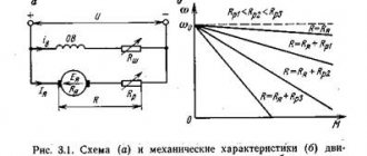
But, despite significant disadvantages, DC motors have a high starting torque and operate stably even at high overloads. Due to their qualities, these units are widely used in electric transport, in the metallurgical and machine tool industries.
However, most modern equipment runs on AC motors. The operation of these devices is based on electromagnetic induction, which is created in a magnetic field by a conducting medium. The magnetic field is created using windings flowing around currents or using permanent magnets. Electric motors operating on alternating current can be synchronous or asynchronous.
The use of synchronous electric motors is practiced in equipment where a constant rotation speed is required. These are DC generators, pumps, compressors and other similar installations. Different models differ in their own technical characteristics. For example, the rotation speed can be in the range of 125-1000 rpm, and the power reaches 10 thousand kilowatts.
Many designs have a short-circuited winding located on the rotor. With its help, if necessary, an asynchronous start is made, after which the synchronous motor continues to operate as usual, minimizing electrical energy losses. These engines are characterized by their small size and high efficiency.
Asynchronous AC motors have become much more widespread in the manufacturing sector. They are characterized by a very high frequency of rotation of the magnetic field, significantly exceeding the speed of rotation of the rotor. A significant disadvantage of these devices is considered to be a decrease in efficiency to 30-50% of the norm at low loads. In addition, during start-up, the current parameters become several times greater compared to operating indicators. These problems are eliminated by using frequency converters and soft starters.
Asynchronous motors are used in those facilities where frequent switching on and off of equipment is required, for example, in elevators, winches, and other devices.
Find out the power connected to the load stabilizer
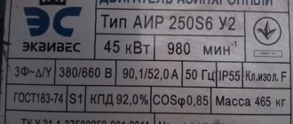
The load power is equal to the sum of the powers of all devices connected to the stabilizer. Before calculating the total power value, it is necessary to find out the energy consumption of each consumer. This is very simple to do: the power of electrical appliances is usually indicated in the technical documentation and is duplicated on the nameplate attached to the product.
Despite the apparent simplicity of the action, at this stage you can make several serious mistakes, which will entail choosing a stabilizer that is not suitable for your tasks.
Particular attention should be paid to equipment for which several capacities are indicated: pumps, heating, sound, climate control equipment, etc. It is important to distinguish between electrical power and the power produced by the product when performing its direct tasks, for example, thermal power for heating boilers, cooling power for air conditioners, sound power for audio systems.
Note!
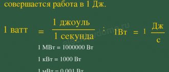
When choosing a stabilizer, you should rely solely on the amount of power consumed by the load from the mains! In the passport of an electrical appliance, this parameter may be called: “power consumption”, “connecting power”, “electric power”, etc. All of the above is a reflection of one quantity - active power, which is measured in Watts (W or W).
Note!
Manufacturers of stabilizers usually build their range of stabilizers based on another quantity - total power, which is measured in Volt-Amps (VA or VA). It is important to understand that Watts and Volt-Amps are not the same thing, and therefore 1000 W is not equal to 1000 VA!
For electrical appliances that contain capacitive components or electric motors, the active and apparent power can vary significantly. Therefore, purchasing a stabilizer designed for 1000 VA with a load of 1000 W may be the wrong decision - the device will be overloaded with all the ensuing consequences.
To avoid this error, you should convert Watts to Volt-Amps and analyze not only the active, but also the total load power. Conversion from Watts to Volt-Amps is carried out by dividing the value in Watts by a special parameter - power factor or cos(φ): VA=W/cos(φ).
Cos(φ) reflects the dependence of the active power of the device on the total. The closer the cos(φ) value is to unity, the less energy is dissipated in the form of electromagnetic radiation and the more is converted into useful work.
The numerical value of cos(φ) is usually (but not always) indicated in the technical documentation of the device consuming alternating current (may be designated as “cos(φ)”, “Power Factor” or “PF”). If the manufacturer has not provided information about the power factor of its product, then for household appliances it is acceptable to take cos(φ) in the range of 0.7-0.8, except for devices that convert electricity into light and heat (incandescent lamps, electric kettles, irons, etc.). etc.), for them the range of power factor values is 0.9-1.
Modern technology, primarily computers, is often equipped with a power supply with power factor correction, which brings this parameter closer to unity - 0.95-0.99. If there is no confidence in the presence of such a function (denoted “PFC” or “KKM”), then for cos(φ) it is recommended to use the value from the typical range indicated in the previous paragraph.
The total load power should be calculated using only the power factor of the equipment corresponding to that load, and not using the input power factor of the stabilizer!
Note!
Devices that have an electric motor in their design are characterized by high starting currents. This category includes: pumps, washing machines and dishwashers, refrigerators, air conditioners, machine tools and compressors. The amount of energy consumed from the electrical network at the moment of turning on any of the above-mentioned devices can be several times higher than the value characteristic of the nominal operating mode.
Manufacturers of this equipment sometimes list the maximum power consumption directly in the characteristics of each model, and sometimes vice versa - they give only the nominal power value, trying not to draw attention to inevitable current surges. We recommend that you carefully study the documentation accompanying any equipment and look for information about the actual power consumed by the device during startup and in various operating modes. The load power is determined using the highest value given for each device!
In addition to mechanisms with electric motors, high starting currents are also typical for lighting devices. And not only with halogen and incandescent lamps, but also with the recently popular LED lamps. LEDs do not have inrush currents, but most luminaires based on them are equipped with capacitors, the inclusion of which causes a sharp increase in current consumption.
When choosing a stabilizer to protect a large lighting system, it should be taken into account that the power value that occurs when such a system is started can be many times higher than the rated value.
Calculation of engine power formula for compressor
When choosing an electric motor that is most suitable for the operation of a particular compressor, it is necessary to take into account the long-term operation of this mechanism and the constant load. The required power of the RDV engine is calculated in accordance with the power on the shaft of the main mechanism. In this case, the losses arising in the intermediate link of the mechanical transmission should be taken into account.
Additional factors are the capacity, purpose and nature of the production where the compressor equipment will be operated. They have an impact and the equipment may require minor but ongoing adjustments to maintain proper performance.
How to correctly take into account the power reserve in electrical panels
When developing a power supply project, the designer has to solve several problems at once:
- Develop a project in accordance with the design assignment and the requirements of regulatory documents;
- Take into account possible modernization of the electrical installation and provide opportunities for their implementation in the project.
As practice shows, electrical loads begin to change even before the facility is put into operation. There may be several reasons:
- During the design they forgot to take something into account;
- The customer came up with new ideas during the implementation of the project;
- The actual purchased equipment has different parameters, etc.
A well-executed power supply project allows such tasks to be implemented with minimal changes to distribution networks and electrical panels.
To take into account such changes, at the design stage, backup circuit breakers are provided in distribution and group electrical switchboards, and the switchboards and supply lines themselves are designed with a reserve capacity.
We’ll talk about how to properly take into account the power reserve in this article.
The reserve must be taken into account not only in the number of reserve machines, in the free space in the switchboard, in the input device and the supply line, but also in the outgoing group lines.
To take this into account, it is necessary not only to ensure the necessary throughput of the lines (margin in the nominal value of the machine), but also to ensure an acceptable voltage drop when the load increases. It is necessary to take into account the increase in voltage drop on the group lines, on the supply line and, as a consequence, the increase in the total voltage drop.
Thus, we need to make two versions of the project:
- According to the original data;
- Taking into account power reserve.
Of course, there is no need to do the second version of the project in full. But you will have to make calculations to provide for automatic machines and cables, taking into account the reserve.
So, on one of the projects that I did, the customer wanted the panels to take into account a 30% power reserve for future development. Those. I had to do the calculations twice.
This is a lot of labor, but I was able to minimize it. When designing, I naturally used DDECAD.
I filled out the shield calculation table...
...and the program automatically calculated the voltage drop for each group.
In this case, the task was posed in such a way that the group lines also had to be able to increase the load by 30%. Those. There were three possible options:
- 30% - these will be new lines;
- The load will be connected to the existing ones;
- The load will be distributed between existing and new lines in some proportion.
How it will actually be is not known at the design stage, so I:
- Provided backup automatic machines in the shields. The rated currents of the machines were similar to those already used in this panel. The quantity was taken in such a way that it would be possible to connect the required future load (30% of the shield power according to the specifications);
- Additionally, he provided a reserve place in the shields in case there were not enough reserve machines;
- I chose machines and cables based on the possibility of increasing the line load by 30%.
To do this, I set the demand factor to 1.3 on group lines. The program automatically recalculated everything for me.
I checked the breaker ratings and voltage drop for each outgoing line. I made sure that the circuit breakers and cables were selected correctly. After that, I set the demand coefficients on the group lines to the initial values and drew the diagram.
conclusions
- To correctly account for the power reserve, you need to:
- Provide a reserve for the capacity of the supply line (machine rating, cable cross-section);
- Provide backup circuit breakers in the panel;
- Provide a reserve space for installing additional machines;
- Keep in mind that as the load on the switchboard increases, the voltage drop in the supply line will increase. As a result, the total voltage drop to the end consumer will increase.
- For design, you should use specialized programs that significantly reduce the time for project development.
Subscribe and receive notifications of new articles by e-mail
Calculation formula for fans
Fans are widely used in a variety of fields. General purpose devices operate in clean air, at temperatures below 80. Air with a higher temperature is moved using special heat-resistant fans. If you have to work in an aggressive or explosive environment, in these cases models of anti-corrosion and explosion-proof devices are used.
In accordance with the principle of operation, fan units can be centrifugal or radial and axial. Depending on the design, they develop pressure from 1000 to 15000 Pa. Therefore, the power required to drive the fan is calculated in accordance with the pressure that needs to be created.
For this purpose, the formula is used: Nв=Hв·Qв/1000·efficiency, in which Nв is the power required for the drive (kW), Hв is the pressure created by the fan (Pa), Qв is the moved volume of air (m3/s), efficiency – efficiency factor.
To calculate the power of an electric motor, the formula is used:
, where the parameter values will be as follows:
- Q – unit productivity;
- Н – outlet pressure;
- ηв – fan efficiency;
- ηп – transmission efficiency;
- short – safety factor depending on the power of the electric motor. With a power of up to 1 kW, short circuit = 2; from 1 to 2 kW short circuit = 1.5; at 5 kW and above short circuit = 1.1-1.2.
This formula allows you to calculate the power of electric motors for centrifugal and axial fans. For centrifugal structures, the efficiency is 0.4-0.7, and for axial ones - 0.5-0.85. Other design characteristics are available in special catalogs for all types of electric motors.
The power reserve should not be too large. If it is too large, the efficiency of the drive will noticeably decrease. In addition, AC motors may experience a reduction in power factor.