Preface
A radio signal, once generated, is carried into the depths of the Universe at the speed of light... This phrase, read in the magazine “Young Technician” in my distant childhood, made a very strong impression on me and even then I firmly decided that I would definitely send my signal to our “brothers in mind” , no matter what it costs me. But the path from desire to dream come true is long and unpredictable...
When I first started getting into radio business, I really wanted to build a portable radio station. At the time I thought it consisted of a speaker, an antenna and a battery. All you have to do is connect them in the correct order and you will be able to talk with friends wherever they are... I filled more than one notebook with possible diagrams, added all kinds of light bulbs, coils and wiring. Today these memories only make me smile, but then it seemed to me that just a little more and I would have a miracle device in my hands...
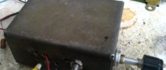
I remember my first radio transmitter. In the 7th grade I went to a sports radio direction finding club (so-called fox hunting). On one of the beautiful spring days, our last “fox” gave orders to live long. The head of the circle, without thinking twice, handed it to me with the words - “... well, you fix it there...”. I was probably terribly proud and happy that I was entrusted with such an honorable mission, but my knowledge of electronics at that time did not reach the “candidate minimum.” I knew how to distinguish a transistor from a diode and had a rough idea of how they work separately, but how they work together was a mystery to me. Arriving home, I opened the small metal box with awe. Inside it was a board consisting of a multivibrator and an RF generator on a P416 transistor. For me this was the pinnacle of circuit design. The most mysterious detail in this device was the master oscillator coil (3.5 MHz), wound on an armored core. Childhood curiosity overpowered common sense and a sharp metal screwdriver dug into the armored casing of the coil. “Gripping,” there was a crunch and a piece of the armored coil body fell to the floor with a thud. While he was falling, my imagination had already painted a picture of me being shot by the leader of our circle...
This story had a happy ending, although it happened a month later. I finally repaired the “Fox”, although to be more precise, I made it anew. The beacon board, made of foil getinax, could not withstand torture with my 100-watt soldering iron, the tracks peeled off due to the constant resoldering of parts... I had to make the board again. Thanks to my dad for bringing (obtained from somewhere with great difficulty) foil getinax, and to my mom for the expensive French red nail polish that I used to paint the board. I couldn’t get a new armor core, but I managed to carefully glue the old one with BF glue... The repaired radio beacon joyfully sent out its weak “PEEP-PEEP” on the air, but for me it was comparable to the launch of the first artificial Earth satellite, which announced to humanity the beginning of space exploration. era with the same intermittent signal at frequencies of 20 and 40 MHz. Here's the story...
Device diagram
There are a huge number of generator circuits in the world capable of generating oscillations of various frequencies and powers. Typically, these are quite complex devices based on diodes, lamps, transistors or other active elements. Their assembly and configuration requires some experience and expensive equipment. And the higher the frequency and power of the generator, the more complex and expensive the devices are needed, the more experienced the radio amateur must be in this topic.
But today, I would like to talk about a fairly powerful RF generator, built on just one transistor. Moreover, this generator can operate at frequencies up to 2 GHz and higher and generate quite a lot of power - from units to tens of watts, depending on the type of transistor used. A distinctive feature of this generator is the use of a symmetrical dipole resonator,
a kind of open oscillatory circuit with inductive and capacitive coupling. Don't be scared by this name - the resonator consists of two parallel metal strips located at a short distance from each other.
I conducted my first experiments with generators of this type back in the early 2000s, when powerful RF transistors became available to me. Since then, I have periodically returned to this topic, until in the middle of summer a topic arose on the website VRTP.ru on the use of a powerful single-transistor generator as a source of HF radiation to jam household appliances (music centers, radio tape recorders, televisions) by directing modulated HF -currents in the electronic circuits of these devices. The accumulated material formed the basis of this article.
The circuit of a powerful RF generator is quite simple and consists of two main blocks:
- Directly the HF self-oscillator itself on a transistor;
- A modulator is a device for periodically manipulating (launching) an RF generator with an audio (any other) frequency signal.
Circuit of the simplest RF generator
A high frequency generator (HHF, in Fig .) is a source of high-frequency sinusoidal oscillations . Their frequency is changed using a variable capacitor C4 in the range from 100 to 550 kHz. The output voltage is adjustable within 0 ... 2 V. Transistor VT1 is connected according to a capacitive feedback circuit, which is carried out through capacitor C3. In the collector circuit of the transistor there is an oscillatory circuit consisting of a coil L1 and a variable capacitor C4. Resistors R1, R2, R4 are included to ensure the required operating mode of the transistor for direct current. For adjustment, use trimming resistor R1. The high frequency voltage is removed from the variable resistor R5, which is used as a generator output voltage regulator. Capacitor C6 is a separation capacitor. If the resistance of the circuit connected to the MHF exceeds 20 ... 30 kOhm (tube stage), then the output voltage is removed through the isolation capacitor C5 from socket X4.
The generator can be used in amplitude modulation . The audio frequency modulating voltage is supplied to socket X1 and through the separating capacitor C1 to the base of the transistor. The modulating voltage changes the mode of the transistor and, accordingly, the amplitude of high-frequency oscillations with the modulation frequency. The modulating voltage source must have an output signal level regulator to select the modulation depth. The source of the modulating signal can be an AF generator.
The generator is powered from a 10V source. Coil L1 is wound on a frame with a diameter of 8 and a length of 25 mm and contains 80 turns of PEV-0.1 wire, wound in bulk. Winding width 10 mm. The ends of the coil are secured to the frame using adhesive tape. As capacitor C4, you can use any dual block of variable capacitors with a suitable capacitance, preferably with an air dielectric. Instead of P416 transistors, you can use any high-frequency transistor of the pnp structure. When replacing the transistor, it may be necessary to adjust the resistor R1. If the parts are in good condition and assembled correctly, the generator starts working immediately after the supply voltage is applied. If there is no generation, instead of resistor R4, install a resistor with a nominal value of 51 kOhm and adjust resistor R1 to achieve normal operation. Otherwise, you need to replace the transistor and select the mode again using resistor R1.\
Mass radio library. A.M. Piltakyan “AMATEUR RADIO DEVICES AND MEASUREMENTS”, publishing house “Radio and Communications”, 1989, pp. 48 – 49.
Similar
Details and design
The “heart” of our generator is a high-frequency MOSFET transistor . This is a fairly expensive and rarely used element. It can be bought at a reasonable price in Chinese online stores or found in high-frequency radio equipment - high-frequency amplifiers/generators, namely, in cellular base station boards of various standards. For the most part, these transistors were developed specifically for these devices. Such transistors are visually and structurally different from the KT315 or MP38 and are “bricks” with flat terminals on a powerful metal substrate. They come in small and large sizes depending on the power output. Sometimes, in one package there are two transistors on the same substrate (source). Here's what they look like:
The ruler below will help you estimate their size. To create an oscillator, any MOSFET transistors can be used. I tried the following transistors in the generator: MRF284, MRF19125, MRF6522-70, MRF9085, BLF1820E, PTFA211801E - they all work. This is what these transistors look like inside:
Internal structure of power MOSFET transistor PTFA211801E
The second necessary material for the manufacture of this device is
copper . You need two strips of this metal 1-1.5 cm wide. and 15-20 cm long (for a frequency of 400-500 MHz). Resonators can be made of any length, depending on the desired frequency of the generator. Approximately, it is equal to 1/4 wavelength. I used copper, 0.4 and 1 mm thick. Less thin strips will not hold their shape well, but in principle they are also functional. Instead of copper, you can also use brass .
Resonators made of alpaca (a type of brass) also work successfully. In the simplest version, resonators can be made from two pieces of wire with a diameter of 0.8-1.5 mm. In addition to the RF transistor and copper, to make the generator you will need a 4093 - these are 4 2I-NOT elements with Schmitt triggers at the input. It can be replaced with a 4011 (4 2I-NOT elements) or its Russian analogue - K561LA7 . You can also use another generator for modulation, for example, assembled on a 555 timer . Or you can completely exclude the modulating part from the circuit and just get an RF generator.
The key element is a composite pnp transistor TIP126 (you can use TIP125 or TIP127, they differ only in the maximum permissible voltage). According to the passport, it can withstand 5A, but it gets very hot. Therefore, a radiator is needed to cool it. Subsequently, I used P-channel field-effect transistors such as IRF4095 or P80PF55 .
LOW FREQUENCY GENERATOR
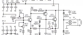
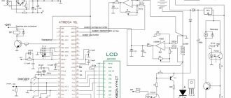
The low frequency generator is assembled using transistors VT1 and VT3. The positive feedback necessary for generation to occur is removed from resistor R10 and supplied to the base circuit of transistor VT1 through capacitor C1 and the corresponding phase-shifting circuit selected by switch B1 (for example, C2, C3, C12.). One of the resistors in the chain is a tuning resistor (R13), with which you can adjust the frequency of generation of a low-frequency signal. Resistor R6 sets the initial bias based on transistor VT1. Transistor VT2 contains a circuit for stabilizing the amplitude of the generated oscillations. The sinusoidal output voltage through C1 and R1 is supplied to the variable resistor R8, which regulates the output signal of the low-frequency generator and regulates the depth of amplitude modulation of the high-frequency generator.
HIGH FREQUENCY GENERATOR
The RF generator is implemented on transistors VT5 and VT6. From the output of the generator, through C26, the signal is fed to an amplifier assembled on transistors VT7 and VT8. An RF signal modulator is assembled using transistors VT4 and VT9. The same transistors are used in the output signal amplitude stabilization circuit. It wouldn’t be a bad idea to make an attenuator for this generator, either T or P type. Such attenuators can be calculated using the appropriate calculators for calculating T-attenuators and P-attenuators. That seems to be all. Goodbye. K.V.Yu.
Download the diagram.
Assembling the device
The device can be assembled either on a printed circuit board or by surface mounting in compliance with the rules for RF mounting. The topology and type of my board are shown below:
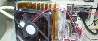
This board is designed for transistor type MRF19125 or PTFA211801E . For it, a hole is cut in the board corresponding to the size of the source (heat sink plate). One of the important points in assembling the device is to ensure heat removal from the source of the transistor. I used various radiators to suit the size. For short-term experiments, such radiators are sufficient. For long-term operation, you need a radiator of a sufficiently large area or the use of a fan circuit. Turning on the device without a radiator is fraught with rapid overheating of the transistor and failure of this expensive radio element.
For experiments, I made several generators with different transistors. I also made flange mounts for the stripline resonators so that they could be changed without constantly heating the transistor. The photographs below will help you understand the installation details.
Flange for mounting resonators
HF generator with replaceable resonators
HF generator with replaceable resonators
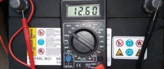
The HF generator operates even at a voltage of 3.6 volts, consuming a current of 2.5A
Rear side of the RF generator
a piece of PCB is also a resonator)))
Flange for replacement resonator
RF generator on a small MOSFET MRF284 with removable resonators
875 MHz. 5W. without much stress...
RF generator on a small MOSFET MRF284 with removable resonators
A family of RF generators based on MOSFET transistors of various powers
Removal of resonator energy to the gate using a capacitor
Two-transistor RF multivibrator
Modulator for RF generator
Experiments with a two-transistor RF multivibrator
Modulator-multivibrator-ballast resistance
Powerful generator-multivibrator using transistors PTFA211801
Small generator on MRF284 1300-1500 MHz.
Small generator on MRF284 1300-1500 MHz.
Small generator on MRF284 1300-1500 MHz.
Sandwich of 3 MRF19125 transistors
Experimental RF generator based on 3 MOSFET transistors
Experimental RF generator based on 3 MOSFET transistors
Experimental RF generator based on 3 MOSFET transistors
Experimental RF generator based on 3 MOSFET transistors
Autogenerator - multivibrator
Three-transistor generator collector board
Checking the operation of the RF generator on PTFA211801E. 6.5 V at 4.6 A.
RF generator with a resonator with an organic glass insert (to fix the shape of the resonant plates).
Checking the operation of the RF generator.
Powerful RF generator board with a cutout for a MOSFET transistor.
The back side of the RF generator: switching, fuse, capacitors and radiator
RF generator board, view from the main installation side.
RF multivibrator + amplifier
RF multivibrator + MOSFET amplifier
Generator board 950-1100 MHz
Generator 950-1100MHz (experimental)
Starting the device
Before starting the generator, you need to double-check that its connections are correct so that you don’t end up with a rather expensive pile of transistors labeled “Burnt.”
It is advisable to carry out the first start-up with control of the current consumption. This current can be limited to a safe level by using a 2-10 Ohm resistor in the generator power circuit (collector or drain of the modulating transistor). The operation of the generator can be checked with various devices: a search receiver, a scanner, a frequency meter, or simply an energy-saving lamp. HF radiation with a power of more than 3-5 W makes it glow.
HF currents easily heat some materials that come into contact with them, including biological tissues. So, be careful, you can get a thermal burn by touching exposed resonators (especially when operating generators with powerful transistors). Even a small generator based on the MRF284 transistor, with a power of only about 2 watts, easily burns the skin of your hands, as you can see in this video:
With some experience and sufficient generator power, at the end of the resonator, you can ignite the so-called. “torch” is a small plasma ball that will be powered by RF energy from the generator. To do this, simply bring a lit match to the tip of the resonator.
T.N. "torch" at the end of the resonator.
In addition, it is possible to ignite an RF discharge between the resonators. In some cases, the discharge resembles a tiny ball of lightning moving chaotically along the entire length of the resonator. You can see what it looks like below. The current consumption increases somewhat and many terrestrial television channels “go out” throughout the house))).
Plasma arc between the resonators of the RF generator on the MRF284 transistor
Analog measuring devices
Rice. 9.5.
High-frequency measuring generators are based on LC—
generators
The resonant frequency of the LC circuit is equal to
. (9.7)
In the generator, a signal of this frequency is amplified and sent to the output, and part of the signal enters the feedback circuit to compensate for losses in the LC circuit.
Let's consider inductive and capacitive three-point generators as examples of LC generators.
One of the embodiments of an inductive three-point
generator
is shown in Fig. 9.6.
Rice. 9.6. Rice. 9.7.
In the diagram Fig. 9.6, capacitance C shunts inductance with tap L, and together they form an LC circuit. Feedback is provided via an RC circuit. The transistor provides a phase shift of 1800, and a shift of another 1800 between the output and the feedback loop is achieved by tapping the inductance L. Capacitor C has a variable capacitance to change the frequency of the oscillator.
One of the capacitive three-point
generator is shown in Fig. 9.7. The circuit uses a transformer output. The circuit is similar to the previously discussed circuit, only instead of an inductance with a tap, two capacitors are used. The generation frequency is calculated using the same formula (9.7), in which C = C1C2 / (C1 + C2). The amount of feedback depends on the values of C1 and C2, it increases when C1 decreases. Resistor R2 causes oscillation damping, so it should not be set too low, and R1C3 provides bias to the base of the transistor.
To obtain the required frequency range, generators are made multi-band with small overlap in ranges. To obtain a large overlap in the range for a given unevenness of the frequency response, beat-based circuits are used. The block diagram of the beat generator is shown in Fig. 9.8.
GPF – fixed frequency generator f0; GFC-oscillator of tunable frequency f + ∆f; SM – mixer; LPF – low pass filter
Rice. 9.8.
The frequency of the output signal changes from 0 to Δf with a relatively small tuning of the frequency of the variable frequency generator (VFO), which makes it possible to ensure the specified unevenness of the frequency response.
The stability of the frequency of the output voltage is determined by the stability of the frequency of the generators of the HPF and GFC and depends on the ratio f0/Δf. The greater this ratio, the higher the demands placed on the generators of the HPF and VHF. The circuits of these generators are made identically so that various factors equally influence both generators and, as a result, the difference frequency remains constant.
The disadvantages of the beat circuit include its relative complexity. In addition, at output signal frequencies close to zero, it is possible to lock onto generator frequencies (self-synchronization). In order to avoid this phenomenon, the generator circuits are carefully shielded and decoupled from the power supply; buffer amplifiers are placed between the generators and the mixer, and this complicates the circuit and design of the beat generators.