Information technology and telecommunications literally permeate all areas of modern life. A visible manifestation of this process is the emergence of such objects as the Smart Home and Smart City, which, as a result of natural evolutionary transformation, are gradually becoming the basis of the digital economy. The intensity of the objective processes of the emergence of digital reality is additionally seriously stimulated from below due to the massive spread of the Internet of Things.
The effective functioning of the digital economy is impossible without telecommunications, the technological basis of which is fiber-optic communication lines. Due to a number of objective reasons, radio communications are used to solve a group of niche problems, since they are actually used in cases where the organization of cable communication channels is physically impossible or impractical for other reasons.
A significant share of the costs of creating a fiber-optic communication line, exceeding half of the total budget, consists of purely construction work. Therefore, the search for ways to save on this cost item is considered one of the priority areas of technology development.
Fiber optic cables for long-distance communications and highways
When choosing routes for laying long-distance cable lines, they are traditionally tied to highways. The choice of such a strategy is determined by the following simple considerations:
- highways connecting populated areas are naturally usually laid in such a way as to minimize their length;
- population and organizations that generate traffic and are consumers of telecommunication services are concentrated in populated areas;
- highways provide the greatest ease of delivery of equipment and various materials along the entire route, both during the construction process and during repair and restoration work after accidents, as well as during routine maintenance.
Additionally, we point out the fact that the highway itself is beneficial from the point of view of the construction of cable communication lines due to the fact that
- the labor-intensive study of the geological basis is excluded from the list of design works;
- due to the presence of bridges, the problem of organizing crossings over water barriers is easily solved;
- due to the homogeneous nature of the soil and the absence of flooding, the risks of cable damage are significantly reduced;
- the requirements for the maneuverability of specialized construction equipment are sharply reduced.
Options for laying fiber optic cables “on the road” and their design
Rice. 1. Schematic representation of a paved road and possible locations for laying cables
Taking into account the above-mentioned natural gravity of the routes for laying cable communication lines to roads, in the general case, three options for the execution of their linear part are possible, which differ in the location of the cable and its design. Cable laying can be done, see fig. 1:
- directly into the road surface (1);
- into the mini-trench of the shoulder (2);
- along the road immediately beyond the right-of-way, usually at a distance of 15 - 30 m from the edge of the roadway (3).
Laying within the right-of-way, but outside the roadside, is permissible if the communication line being created is intended to solve service problems necessary for the correct functioning of the route. This possibility is not specifically identified as a separate option due to the fact that from the point of view of performing construction work, with the exception of organizational issues, it is practically no different from laying an alienated strip outside its boundaries.
It is possible to lay it directly in the road surface in its side part at a depth of about 10–15 cm in a groove about 2 cm wide, followed by filling with tar. This technology was actively promoted by the German company Siemens at the very beginning of the 2000s and was partially in demand in the city. As a prototype of the cable used for this, Fig. 1b, due to the need to ensure high lateral strength, a deep sea cable module was selected. It differed from the widespread traditional “land” products in that it contained a thick-walled copper or aluminum tube, which served as a power base and waist insulation. Due to the high cost of such products (at least 1.5 times more compared to traditional structures with armor made of round steel wire due to the use of a continuous reinforcing coating made of non-ferrous metal of large thickness), this direction of development has not received.
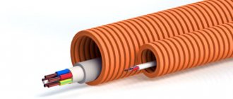
Rice. 2. Schematic representation of cable options for laying along paved roads: a) traditional modular design in single-layer armor made of round steel wire; b) with continuous tubular armor; c) armorless with a tube for pneumatic laying
Laying outside the right-of-way is carried out directly into the ground and should only be done with a cable armored with steel wire. The wire has a predominantly round cross-section; the more efficient square-cross-section wire is not used due to the technological difficulties of applying it to the cable body. The most common designs are with single-layer armor, Fig. 2a, when laying in rocky soils and when there is a risk of frozen soil deformations, 2-layer wire armor can be used, which allows the permissible tensile force of the cable to be increased to 20 tons.
As-built documentation
Rules for laying a communication cable near a regional road.
So, you suddenly found out that the section of road next to which you have to lay a communication line is a road of regional significance. What does this mean and how to act correctly in this case?
First of all, it is necessary to request technical conditions for the construction of a communication line near a regional road. The letter is written to the Head of the State Public Administration for the region in which the road belongs.
Approximate contents of the technical specifications:
Head of GKU TO A.A. Antoinova
Features of the implementation of the linear part of the fiber-optic cable system laid on the road
For constructing the linear part of a fiber-optic communication system at the roadside, the most suitable technology is pneumatic laying, which complies with the recommendations L.48, L.49 and L.68 of the International Telecommunication Union. The technology is based on the use of a combination of tubes and armorless cables, Fig. 2c. The idea of this technology and its main properties were discussed in the article “Blowing an optical cable: pneumatic fiber-optic installation technology, features, application.” Therefore, further we will dwell only on the differences from the traditional scheme for implementing long-distance communication lines.
Roadside installation requires a few simple procedures.
Rice. 3. Dimensions of minitrenches in the roadside structure
First, using a chain saw or circular saw, a slot (mini-groove or mini-trench) 5–10 cm wide and approximately 50–60 cm deep is formed in the body of the roadside, see Fig. 3. The plow-propeller, which is popular for underground laying of long-distance lines, in this case is rather redundant due to absence of such a need - the structure of the roadside initially assumes that there are no tree roots, boulders and other similar invisible underground obstacles.
Every kilometer, at branches from the road, as well as at other points provided for by the project, a recess is formed for installing a prefabricated plastic well into it. The choice of a distance between wells of 1 km is due to the desire to create technical reserves (the maximum length of the tube can reach 1.5 km), so that a slight excess of this distance does not lead to serious consequences.
The well can withstand pressure up to 26 tons. This value exceeds the normative static axle load of the vehicle according to the updated edition of SNiP 2.05.02-85 by more than a double margin. Thus, there is no danger of its destruction when pulling onto the side of the road, even with heavily loaded trucks.
Single tubes for armorless cables or their assemblies-packages with a common shell, placed in the cut immediately after its formation, have two standard sizes with a difference in diameter of two times. This feature additionally has a small standard depth of the minitrench, which creates conditions for the ease of changing its width, allows you to flexibly vary the number of fibers in the linear part and easily adapt the structure of the highway telecommunications network to the needs of a specific project, Fig. 4. Laying single tubes and their packages in a trench and restoring the integrity of the roadside can be done from one vehicle.
Rice. 4. Possible options for placing combinations of tubes in minitrenches of different widths (wide on the left, narrow on the right)
The tractor on which the sawing unit is installed has relatively moderate power, which has a positive effect on its dimensions. While working, he moves along the side of the road. The excavation for the wells has small dimensions. All this is beneficial from the point of view that it allows not only not to stop traffic on the road, but not even to impose restrictions on it.
To penetrate under level roads, the popular technology of horizontal directional drilling is used. River crossings are carried out on bridges using additional mechanical protection of tubular cables originally designed for operation in such conditions.
After the formation of the tubular channel system, the armorless mini-cables are blown in, which requires the use of a special technological device, for example, Katimex X-Blow micro. It has good weight and dimensions, which allows it to be stored together with accessories in a suitcase when not in use, Fig. 5.
Rice. 5. Head for inserting and advancing an optical mini-cable in a tubular channel with a connected source of compressed air and mounted on a tripod - Katimex X-Blow micro
Next, the usual procedures for working with the linear part of fiber-optic communication are performed:
- welding of individual construction lengths with the installation of couplings or reinforcement of individual fibers with connector elements with their subsequent connection to cross-connect sockets at intermediate and end points of the route, respectively;
- checking the overall attenuation and absence of defects at operating wavelengths;
- preparation of the necessary documentation (certification of the route).
The last step is to connect to active network equipment.
Additional protection of the cable from moisture is not required, which is provided
- the absence of risks of constant presence of water in wells located in the thickness of the roadside above the level of the aquifer;
- the use of moisture-proof coatings for pipes and the tightness of the structure of the prefabricated well;
- moisture-resistant polyethylene sheath of the minicable;
- filling the internal voids of the cable core with hydrophobic gel.
The main advantages of laying an optical cable on the side of the road
Using the roadside as a location to install fiber optic cable has several advantages over traditional off-right-of-way installations. Among the most significant among them, the following factors deserve special mention:
- high laying speed, which is illustrated by the data in Table 1;
- ease of installation of wells, determined by their prefabricated design, low weight and small dimensions;
- minimizing the risks of frozen deformations and prolonged exposure to moisture, determined by the structure and conditions of formation of the roadside;
- ease of connection to the information system of technological controllers for various purposes, facilitating the ongoing operation of highways and making road traffic more efficient.
Table 1. Typical parameters for the construction of the linear part of a fiber-optic communication system
| Route Component | Traditional technology | Pneumatic gasket |
| Linear part | 1 km per shift | 3 km per shift |
| Well installation | 4 hours | 1 hour |
It is of no small importance that the risks of damage to cables and wells by construction equipment during operation are reduced to almost zero (the availability factor of the linear part of the system reaches “five nines” or 0.99999) simply due to the absence of construction work carried out by third parties on the side of the roads.
From a financial point of view, a road telecommunications network at the construction and operation stages costs the customer and operator at least tens of percent less. If in terms of capital costs this statement is not unexpected due to the simplicity and low cost of construction mechanisms, as well as good weight and size indicators of cables, then in terms of operation everything is not so obvious and requires additional comments.
The added benefit of lower operating costs for organizations designing, building and operating technology information systems directly results from the ease of adding individual fibers to a line and/or feeding them to an intermediate point along the route as the need arises. A fiber-optic long-distance communication line is a highly capital-intensive facility; building up the traffic transmitted over it to its design capacity sometimes takes ten years or more. Given the high cost of borrowing, the ability to implement a fiber-on-demand approach allows the operator to save significant financial resources.
What are the advantages of the puncture method?
During a trenchless transition, special steel cases are used, which are pushed by a pump-jacking unit into the developed well with translational movements, due to which the soil does not crumble.
Advantages compared to other methods:
- Lower price.
- Reduced work time.
- No additional arrangement of the work area is required.
- Groundwater does not affect the process, so there is no need to dewater when installing a utility network using the puncture method.
- Upon completion of the work, there is no need to restore the surface or recreate the paths.
Work on and under railway tracks is complex and dangerous and is therefore carried out exclusively by qualified specialists. To use the HDD installation, it is necessary to prepare the site for its placement.
If it is necessary to carry out work in rocky or hard soils and to place large-diameter communications, then the trenchless drilling method is used.
Safety regulations during HDD drilling are developed to ensure the protection of the health and lives of members of the working team, and to reduce the risk of breakdown of the equipment used.
Persons at least 18 years of age are allowed to work with drilling rigs. Before starting construction work, they must undergo a medical examination, followed by instruction, and then confirm their knowledge and skills in an exam.
Before using any equipment, each worker must thoroughly study the instructions provided by the supplier and ultimately comply with the operating conditions. The installations and work site are kept in a condition that satisfies the instructions. No strangers are allowed on the work site.
During breaks between work processes, builders are prohibited from settling on the ground or in grass, bushes - areas located near the operation of drilling rigs. The staff must have a specially designated and equipped room that meets hygienic standards, in which they can dry their clothes, take a lunch break, and rest if necessary. It is imperative to have a first aid kit containing all the necessary medications to be able to immediately provide first aid.
Potential consumers of optical cables in the roadway
When determining the list of potential consumers of road telecommunications network resources, it is necessary to take into account the strongest aspects of the technology for pneumatic laying of fiber-optic cable in tubes, which directly follow from the scheme of its implementation. The main ones are the short time it takes to build such a line after laying the pipes and its high flexibility in terms of ease of diversion every kilometer and at intersections with other roads, even if this was not provided for in the original project. We also take into account the installation location - the side of the road. Therefore, along with traditional consumers of fiber-optic communication line resources, which are:
- public communication network operators;
- distributed network of data centers implemented in the country;
- operators of departmental networks (energy, pipeline transport), who often use general purpose communication lines to increase the operational survivability of their networks through mutual redundancy;
- cellular base stations
Numerous terminal devices of the information infrastructure newly created along the highway can be connected to the created communication line. The list of these includes:
- traffic control cameras;
- controllers for controlling the lighting system;
- autonomous weather stations;
- emergency telephone numbers for rescue services;
- information boards;
- inductive loop sensors of mass and axial load on the road surface;
- readers for contactless payment systems for travel on toll highways.
If necessary, the list of consumers can be continued.
Crossing the cable with the road
To equip intersections with railway tracks and roads, blocks, protective pipes or tunnels are used for the installation of cable lines (clause 2.3.97.). These protective measures apply to the entire exclusion zone of the road being crossed. The cable line is installed in the specified area with a recess of at least 1 meter from the road surface and at least half a meter from the bottom of the ditches used for drainage.
In cases where an exclusion zone for the road being crossed has not been established, the described conditions for installing cable lines are fulfilled in an area that includes the intersection and 2-meter sections on each side of the roadway.
If the railway track crossed by the cable is electrified with direct current voltage, or such electrification is pending, all protective devices - blocks, pipes used when laying cable lines must be made of insulating material.
During the design process of a cable line, the place where it intersects with the railway track is selected in such a way that the distance from it to turnouts, crosses and rail connections with suction lines is at least 10 meters. The angle at which the cable line intersects with the railway track should be in the range from 75° to 90°.
important:
For more information about which cable is best used for underground installation, read our article “Cable for installation in the ground”
The ends of pipes or blocks used to protect cable lines must be located in a recess of at least 300 mm from the ground surface. Installation of a cable line crossing lightly loaded industrial roads (dead ends, etc.) is carried out directly in the ground.
If a non-electrified railway line or road under construction crosses a previously laid cable line, relaying the cable line is not required. In this case, it is necessary to lay pipes or blocks along the cable line through which the cable can be passed when repairing the cable line. The ends of pipes and blocks should be reliably protected from clogging with soil.
Intersections of cable lines with city tram tracks are carried out no closer than 3 meters from turnouts and connection of suction stations. The cables are laid in pipes made of insulating material.