Check on the motherboard
So, when the board's power is turned on, the protection is triggered. First of all, you need to check the resistance of the stabilizer arms with a multimeter.
A radio components tester can also be used for these purposes. If one of them shows a short circuit, that is, the measured resistance is less than 1 Ohm, then one of the key field-effect transistors is broken.
Identifying a broken transistor if the stabilizer is single-phase is not difficult - a faulty device, when checked with a multimeter, shows a short circuit. If the stabilizer circuit is multiphase, and this is how the processor is powered, parallel connection of transistors takes place. In this case, you can determine the damaged device in two ways:
- dismantle the transistor and check the resistance between its terminals with a multimeter for breakdown;
- Without soldering the transistors, measure and compare the resistance between the gate and source in each phase of the converter. The damaged area is identified by a lower resistance value.
The second method does not work in all cases. If the broken element could not be determined, you will still have to unsolder the transistor.
Next, the damaged transistor is replaced, and all radio elements that were soldered off during the diagnostic process are replaced. After this, you can try to start the board.
The first startup after repair is best done by removing the processor and setting the appropriate jumpers . If the first run was successful, you can carry out a load test, monitoring the temperature of the mosfets.
Malfunctions of the PWM controller can manifest themselves in the same way as a breakdown of the mosfets, that is, the power supply goes into protection. At the same time, checking the transistors themselves for breakdown does not give any results.
In addition, the consequence of a malfunction of the PWM controller may be the absence of output voltage or its discrepancy with the nominal value. To check the PWM controller, you should first study its datasheet. The presence of high-frequency voltage in pulse mode, in the absence of an oscilloscope, can be determined using a quartz tester on a microcontroller.
How to check the UC3842 chip
The UC3842 PWM controller chip is the most common in the construction of monitor power supplies. In addition, these microcircuits are used to build switching voltage regulators in horizontal scanning units of monitors, which are both high-voltage stabilizers and raster correction circuits. The UC3842 chip is often used to control the key transistor in system power supplies (single-cycle) and in power supplies for printing devices. In a word, this article will be of interest to absolutely all specialists in one way or another connected with power supplies.
Failure of the UC 3842 microcircuit occurs quite often in practice. Moreover, as the statistics of such failures show, the cause of a microcircuit malfunction is a breakdown of a powerful field-effect transistor, which is controlled by this microcircuit. Therefore, when replacing the power transistor of the power supply in the event of a malfunction, it is strongly recommended to check the UC 3842 control chip.
There are several methods for testing and diagnosing a microcircuit, but the most effective and simplest for practical use in a poorly equipped workshop are checking the output resistance and simulating the operation of the microcircuit using an external power source.
For this work you will need the following equipment:
- 1) multimeter (voltmeter and ohmmeter);
- 2) oscilloscope;
- 3) a stabilized power source (current source), preferably regulated with a voltage of up to 20-30 V.
- checking the output resistance of the microcircuit;
- modeling the operation of the microcircuit.
There are two main ways to check the health of the microcircuit:
The functional diagram is shown in Fig. 1, and the location and purpose of the contacts in Fig. 2.
Checking the output resistance of the microcircuit
Very accurate information about the health of the microcircuit is provided by its output resistance, since during breakdowns of the power transistor, a high-voltage voltage pulse is applied precisely to the output stage of the microcircuit, which ultimately causes its failure.
The output impedance of the microcircuit must be infinitely large, since its output stage is a quasi-complementary amplifier.
You can check the output resistance with an ohmmeter between pins 5 (GND) and 6 (OUT) of the microcircuit (Fig. 3), and the polarity of connecting the measuring device does not matter. It is better to make such a measurement with the microcircuit soldered off. In the event of a breakdown of the microcircuit, this resistance becomes equal to several ohms.
If you measure the output resistance without unsoldering the microcircuit, then you must first unsolder the faulty transistor, since in this case its broken gate-source junction may “ring.” In addition, it should be taken into account that the circuit usually has a matching resistor connected between the output of the microcircuit and the “case”. Therefore, when tested, a working microcircuit may have an output resistance. Although, it is usually never less than 1 kOhm.
Thus, if the output resistance of the microcircuit is very small or has a value close to zero, then it can be considered faulty.
Simulation of microcircuit operation
This check is carried out without unsoldering the microcircuit from the power supply. The power supply must be turned off before performing diagnostics!
The essence of the test is to supply power to the microcircuit from an external source and analyze its characteristic signals (amplitude and shape) using an oscilloscope and voltmeter.
The operating procedure includes the following steps:
- 1) Disconnect the monitor from the AC power supply (disconnect the power cable).
- 2) From an external stabilized current source, apply a supply voltage of more than 16V (for example, 17-18V) to pin 7 of the microcircuit. In this case, the microcircuit should start. If the supply voltage is less than 16 V, the microcircuit will not start.
- 3) Using a voltmeter (or oscilloscope), measure the voltage at pin 8 (VREF) of the microcircuit. There should be a reference stabilized voltage of +5 VDC.
- 4) By changing the output voltage of the external current source, make sure that the voltage on pin 8 is stable. (The voltage of the current source can be changed from 11 V to 30 V; with a further decrease or increase in voltage, the microcircuit will turn off and the voltage on pin 8 will disappear).
- 5) Using an oscilloscope, check the signal at pin 4 (CR). In the case of a working microcircuit and its external circuits, there will be a linearly varying voltage (sawtooth-shaped) at this contact.
- 6) By changing the output voltage of the external current source, make sure that the amplitude and frequency of the sawtooth voltage at pin 4 is stable.
- 7) Using an oscilloscope, check for the presence of rectangular pulses on pin 6 (OUT) of the microcircuit (output control pulses).
If all of the indicated signals are present and behave in accordance with the above rules, then we can conclude that the chip is working properly and is functioning correctly.
In conclusion, I would like to note that in practice it is worth checking the serviceability of not only the microcircuit, but also the elements of its output circuits (Fig. 3). First of all, these are resistors R1 and R2, diode D1, zener diode ZD1, resistors R3 and R4, which form the current protection signal. These elements often turn out to be faulty during breakdowns
Symptoms of malfunction and their elimination
Let's move on to consider specific symptoms of PWM controller malfunctions.
- MP2359DJ is a good small PWM controller
Stopping immediately after starting
The pulse modulator starts but immediately stops. Possible reasons: open feedback circuit; the power supply is overloaded; The filter capacitors at the output are faulty.
Finding the problem: inspecting the board, looking for visible external damage; Using a multimeter to measure the supply voltage of the microcircuit, the voltage on the switches (at the gates and at the output), and on the output capacitors. In ohmmeter mode, use a multimeter to measure the load of the stabilizer and compare it with the typical value for similar circuits.
Pulse modulator does not start
Possible reasons: presence of a prohibiting signal at the corresponding input. Information should be found in the datasheet of the corresponding microcircuit. The malfunction may be in the power supply circuit of the PWM controller, or there may be internal damage in the microcircuit itself.
Steps to determine the malfunction: external inspection of the board, visual search for mechanical and electrical damage. To check, use a multimeter to measure the voltages on the pins of the microcircuit and check their compliance with the data in the datasheet; if necessary, you need to replace the PWM controller.
Voltage problems
The output voltage differs significantly from the nominal value. This can happen for the following reasons: a break or change in resistance in the feedback circuit; a fault inside the controller.
Troubleshooting: visual inspection of the circuit; checking the levels of control and output voltages and checking their values with the datasheet. If the input parameters are normal, but the output does not correspond to the nominal value, replace the PWM controller.
Disabling the power supply by protection
When the pulse-width modulator starts, the power supply is turned off by protection. When checking the key transistors, a short circuit is not detected. Such symptoms may indicate a malfunction of the PWM controller or key driver.
In this case, it is necessary to measure the resistance between the gate and source of the switches in each phase. A low resistance value may indicate a driver malfunction. If necessary, drivers are replaced.
Forum list » Household appliances
»
Washing machines and dishwashers
- How to check a triac with a multimeter so as not to buy a new part?
| Author | Message |
| 12-03-2015 20:40 |
DZ3 can be called back without desoldering it from the board, its nominal value is 3V9
Warnings: 1 Messages: 12
Comments 30
In general, all electrolytes need to be replaced, and then the rest from blown alloys rarely burns, the key should burn out first, followed by the switch (not always)
Are they all blind? The conder is blown! Change it, then the rest...
I guess I'm blind if I didn't bother to read all the comments. Below we have already paid attention to it.
Look at the thermal fuse, it should be on the body of the flask itself, it blew out.
change the PWM VIPER12A, the largest high-voltage condenser and everything will work.
easy to say - change: we don’t sell r/d
- PWM controller chips UC3844, UC3845, UC2844, UC2845
Read also: What tools does a carpenter need for work?
The model is written on the board under the wire, so look for the diagram using it
thermopot... thermopot... thermopot)
Your air conditioner seems to be swollen on the left side near the mikruhi. change it
and what doesn't work?
I usually start by looking for a circuit, a cartoon with testing capacitances up to 20 µF
The capacity may be normal, but the internal EPS large
only with eser meter or replacement
Your air conditioner seems to be swollen on the left side near the mikruhi. change it
change and check the diodes...
Pulse-width converters are a structural part of switching power supplies for electronic devices. Let's look at how to check a PWM controller using a multimeter, using the example of a computer motherboard.
When repairing various radio equipment, it is sometimes necessary to replace some small but complex microcircuits that have failed, such as PWM controllers, but there are no original radio components. And buying them is also problematic. That’s when you have to look for analogues - substitutes for the original PWM.
The concepts “analog” and “interchangeable” are not the same thing.
Analogue implies complete functional and output coincidence (so to speak, but-ga-vno-gu). For example, different companies may produce the same device, but under different names. Fungibility is a broader concept. For example, some devices are almost identical in pinout (for example, they differ in one of the pins functionally), but can be used for mutual replacement where this pin is not used. I would like accuracy - so that it is clear what is being discussed in each paragraph of this entry: where about interchangeability, and where analogues are given. And where the devices are not complete analogues, I will indicate: “interchangeable there and there.”
1. RT8207GQW DDRII/DDRIII Memory Power Supply Controller and TPS51116RG DDR, DDR2 and DDR3 Memory Power Solution Synch Buck Controller Interchangeable (source: - ZG5 circuit (AO110/150), page 30)
difference: - for RT8207, pin 12 is TON The pin is used to set the UGATE on time through a pull-up resistor connecting to VIN (R = 620k), while for TPS51116RG it is not used. DDR-II - complete interchange (including pin 12) DDR-III - If in the circuit the 9th pin is connected via “FB Resistors RUP= RDOWN=75 kΩ” then you don’t need to do anything, pay attention only to the 12th pin. If the 9th pin is connected to ground, and we want to change from RT8207GQW to TPS51116RG, then we need to disconnect the 9th pin from GND and organize “FB Resistors RUP= RDOWN=75 kΩ” (otherwise we will get not 1.5 V at the output, but 2.5!!). If you change the other way around, from TPS51116RG to RT8207GQW, then the 9th pin can simply be short-circuited to ground, or the lower resistor can be set to 0 (jumper). Installed on Samsung R469 (ddr2) tps51116 instead of rt8207b, taking into account all the recommendations. DOES NOT WORK! We installed rt8207b, everything works. So it doesn’t fit everywhere, and on some Samsungs it fits, you only need to connect 18 (GND) to 17 (sc_gnd).
2. RT8205B, RT8223B (DS=CC), TPS51123, TPS51125 - analogues. In the Toshiba Satellite A660, A665 laptop - Compal LA-6062P (REV.2.0 - NWQAA Marseille 10G) - according to the scheme there is an RT8205B, on the TPS51125 board. TPS51123 is easily replaced by TPS51125 - the flight is normal, the latter is more common on sale than those listed above. There are still differences. I suspect that a reverse replacement with RT8205 is not always possible. TPS51125 can be successfully replaced with TPS51123, you just need to throw a jumper from pin 8 to pin 18.
3. ISL6237, RT8206B, TPS51427, TPS51427A - interchangeable with each other. According to the scheme Acer Aspire 5742G - Compal LA-5893P (r1.0) there is RT8206B and at the same time some signals are marked as from ISL6237.
4. MAX8778=MAX17020, ISL6236, ISL6236A, PM6686, RT8206A, SN0608098 - interchangeable with each other. HP DV6940er - Quanta AT3 Rev. F - costs ISL6236 (according to the MAX8778 scheme).
5. ISL6262 and ISL9504 are analogues.
6. RT8209B (A0=), TPS51117, RT8202B - identical in pinout. RT8202B - differs in 11 pin (a resistor is installed between this pin and PHASE).
7. RT8208B (FG=) and SC411 - identical in pinout.
8. MAX8732, 8733, 8734 pin-for-pin upgrades MAX1777, 1977, 1999
9. MAX17005, 17006, 17015, MAX17005A, 17006A, 17015A, MAX17005B, 17006B, 17015B - analogues
10. APW7138 and ISL6268 are analogues.
11. APW7108, FAN5236, ISL6227 - analogues. According to the diagram for RoverBook B515 - ECS U50SI1, Rev: C - it costs ISL6227. The board contains APW7108. Samsung NP R20 - was a successful replacement of ISL6227 with FAN5236.
12.Replacing OZ2216S with TPS2216 (only in SS0P-30 case) solved the problem.
13.MAX8724 - MAX1908 - MAX8765
14.MAX8725 - MAX1909
15. MAX1631 is interchangeable with MAX1634 , but in the case of MAX1631 there is a built-in overvoltage and undervoltage protection circuit, which is not present in the MAX1634.
16. MAX1630–MAX1635 are almost interchangeable PWMs with some nuances. From the datasheet on the MAX1630:
The MAX1630–MAX1635 include two PWM regulators, adjustable from 2.5V to 5.5V with fixed 5.0V and 3.3V modes. All these devices include secondary feedback regulation, and the MAX1630/MAX1632/MAX1633/MAX1635 each contain 12V/120mA linear regulators. The MAX1631/MAX1634 include a secondary feedback input (SECFB), plus a control pin (STEER) that selects which PWM (3.3V or 5V) receives the secondary feedback signal. SECFB provides a method for adjusting the secondary winding voltage regulation point with an external resistor divider, and is intended to aid in creating auxiliary voltages other than fixed 12V. The MAX1630/MAX1631/MAX1632 contain internal output overvoltage and undervoltage protection features.
If you carefully read the datasheet, then MAX1631 (without modification) is interchangeable with MAX1634, but in principle it cannot be changed with MAX1630, MAX1632, MAX1633, MAX1635 without modification. All this is written down in the datasheet. In turn, the MAX1630/MAX1633 chips are interchangeable and the MAX1632/MAX1635 are interchangeable. MAX1631 is changed to MAX1632, legs 4 and 5 are left in the air (5 is the input of the 12v linear stabilizer, 4 is its output) tested in the IBM T42.
17. Richtek RT8202 is very similar to UP6111AQDD . The latter is found in the Acer Aspire One (ZG8). Same pinout for UP6128A . Another analogue of G5602R41U , used in the circuit from Quanta HK5.
18. MAX17415 changes to MAX17015 .
19. APL5331, APL5336, RT9173D, G2992, AP1280MP - analogues. According to the LA-5893P circuit, there is an APL5336 (PU21) - at VIN 1.5V, at VOUT - 0.75V. According to the LA-4602P circuit, there is an APL5331 with the same VIN, VOUT, and on the board there is an RT9173D. Replacing APL5336 (PU21) with APL5331 in Acer Aspire 5742 (Compal LA-5893P, r1.0) was successful.
20.RT9045=uP7711U8=FP6137E
21. AP2101=G547 usb power switch. Board CHICAGO_BR_HPC MV_MB_V2.
22. G5209 is replaced by isl6251 in LA-6552P.
23. MAX1532A, MAX8760 - analogues The Acer TravelMate 4150 (Compal LA-2602) had a MAX1532A on the board - it is being replaced by the MAX8760.
24. P2806, G5934 - analogues.
25. OZ8111, OZ8116, OZ8118 - analogues. The Quanta NE7 schematic shows OZ8111LN, but the pins are labeled from OZ8116. The Quanta ZR6 schematic shows OZ8111, but the page is titled OZ8118. The circuits are interchangeable without alteration, but their power differs significantly, that is, the replacement may not be correct for every circuit, although for laptops the replacement is correct. Before replacing, be sure to look at the datasheet to check the maximum power consumption. !!! 8116 and 8118 are different in size.
26. A few words about the interchangeability of SC475A and the non-interchangeability of SC471 and SC471A . The specified m\s have identical pinouts, and the output field switches are open source D0 (D1), controlled by the inputs G0 (G1). In switching circuits, these switches are used to regulate the output voltage rating. Moreover, for SC471 the inputs G0, G1 are direct, and for SC471A they are inverse (in SC471 the keys D0, D1 are opened with “one”, and in SC471A with zero), SC475A has only one channel - G0, D0 with inverse control. Accordingly, SC475A can be successfully replaced by SC471A in any circuit (you just need to make sure that the unused pin 7 of SC475A on the board is not accidentally connected anywhere, because for SC471A this is output D1). It is absolutely clear that SC471 and SC471A are not interchangeable without inverting the input signals G0, G1. However, for those who know a lot about perversions, this is not a hindrance - if you wish, you can push two N-fields with pullups on the drains at the G0, G1 inputs...
27.SY8033BDBC_DFN10_3X3, BP0QA, BP1BE, BP1GG, BP1IG, BP9ZA.
28. G5603 was successfully changed to TPS51117 on the LA-6552P laptop board (formed +1.1VALWP).
29. TPS51117RGY (QFN package) = APW7141QAITRG . according to the Samsung R525 Bremen-D scheme it costs APW7141QAITRG, physically - TPS51117RGY; the harness around it was demolished (with a screwdriver?) and successfully restored according to the diagram.
30. 2952 or 2952a = FT484 = MP1410 = G5795 - replacement. Many Chinese tablets and netbooks contain the simplest PWM converter - an eight-legged planar in the simplest SOP-8 package labeled 2952 or 2952a. When using the MP1410, you need to take into account that it does not have a soft start (pin 8 is not used), and has slightly different ratings in the harness (see datasheet).
31. RT9045 <= APL5336 - replacement. (VTT DDR) The replacement was an Asus N53T.
32. HPA00835RTER = tps54418 - analog. The conclusion was made based on a comparison of the mother and the ZH9 circuit; the circuit is one thing, but the board is different.
33.On Samsung NP350V5C, platforms LA-8861P, LA-8862P are interchangeable with each other: APW8812, RT8205L, TPS51125 . The first two are running normally.
34. On the Quanta R33, according to the diagram, there is UP1585QQAG , in fact - RT8223MGQW . Replacement - TPS51123 .
35. UP6111AQDD = RT8202 = Sc411 - analogs.
36.Toshiba C660-13Q LA-6842P. According to the diagram - S IC UP6182CQAG , on the board there is TPS51125A .
37. BQ24725A => BQ24735 on asus x550dp, replacement successful.
38. G5603RU1U TQFN14 3P5X3P5 successfully replaced with TPS51117 laptop motherboard LA-6842P, memory power supply.
39. TPS51212 - analogue of RT8237E . In Compal LA-7912 according to the TPS51212 circuit, on the RT8237E board.
40. RT8859M can be replaced by ASP1000RM EPU (used on Asus boards). Tested on Acer IPISB-AG Rev. 1.06.
41.Compal LA-7981, charger BQ24727 is replaced by BQ24707 , since pin 11 is not used.
42. Wistron JE40-HR , according to the BQ24745 circuit, on the ISL88731 , the resistor on the 7th leg is not soldered.
43. RT8209MGQW => TPS51212DSCR => TPS51218DSCR successful replacement for LA-8331P.
44. ISL6520 = LD7120 => APW7057 => FAN6520 => NCP1580 => NCP1582 => ISL6545 => l6727 => l6726 => RT9214 => RT9202
Call or leave a request directly on the website! Our specialists will be happy to help you!
Check on the motherboard
So, when the board's power is turned on, the protection is triggered. First of all, you need to check the resistance of the stabilizer arms with a multimeter.
Read also: Regulating the speed of a brushed motor without loss of power
A radio components tester can also be used for these purposes. If one of them shows a short circuit, that is, the measured resistance is less than 1 Ohm, then one of the key field-effect transistors is broken.
Identifying a broken transistor if the stabilizer is single-phase is not difficult - a faulty device, when checked with a multimeter, shows a short circuit. If the stabilizer circuit is multiphase, and this is how the processor is powered, parallel connection of transistors takes place. In this case, you can determine the damaged device in two ways:
<
dismantle the transistor and check the resistance between its terminals with a multimeter for breakdown; without soldering the transistors, measure and compare the resistance between the gate and source in each phase of the converter. The damaged area is identified by a lower resistance value.
The second method does not work in all cases. If the broken element could not be determined, you will still have to unsolder the transistor.
Next, the damaged transistor is replaced, and all radio elements that were soldered off during the diagnostic process are replaced. After this, you can try to start the board. The first startup after repair is best done by removing the processor and setting the appropriate jumpers . If the first run was successful, you can carry out a load test, monitoring the temperature of the mosfets.
Malfunctions of the PWM controller can manifest themselves in the same way as a breakdown of the mosfets, that is, the power supply goes into protection. At the same time, checking the transistors themselves for breakdown does not give any results. In addition, the consequence of a malfunction of the PWM controller may be the absence of output voltage or its discrepancy with the nominal value. To check the PWM controller, you should first study its datasheet. The presence of high-frequency voltage in pulse mode, in the absence of an oscilloscope, can be determined using a quartz tester on a microcontroller.
Symptoms of malfunction and their elimination
Let's move on to consider specific symptoms of PWM controller malfunctions.
Stopping immediately after starting
The pulse modulator starts but immediately stops. Possible reasons: open feedback circuit; the power supply is overloaded; The filter capacitors at the output are faulty. Finding the problem: inspecting the board, looking for visible external damage; Using a multimeter to measure the supply voltage of the microcircuit, the voltage on the switches (at the gates and at the output), and on the output capacitors. In ohmmeter mode, use a multimeter to measure the load of the stabilizer and compare it with the typical value for similar circuits.
Read also: DIY pullers for the garage
Pulse modulator does not start
Possible reasons: presence of a prohibiting signal at the corresponding input. Information should be found in the datasheet of the corresponding microcircuit. The malfunction may be in the power supply circuit of the PWM controller, or there may be internal damage in the microcircuit itself. Steps to determine the malfunction: external inspection of the board, visual search for mechanical and electrical damage. To check, use a multimeter to measure the voltages on the pins of the microcircuit and check their compliance with the data in the datasheet; if necessary, you need to replace the PWM controller.
Voltage problems
The output voltage differs significantly from the nominal value. This can happen for the following reasons: a break or change in resistance in the feedback circuit; a fault inside the controller. Troubleshooting: visual inspection of the circuit; checking the levels of control and output voltages and checking their values with the datasheet. If the input parameters are normal, but the output does not correspond to the nominal value, replace the PWM controller.
Disabling the power supply by protection
When the pulse-width modulator starts, the power supply is turned off by protection. When checking the key transistors, a short circuit is not detected. Such symptoms may indicate a malfunction of the PWM controller or key driver. In this case, it is necessary to measure the resistance between the gate and source of the switches in each phase. A low resistance value may indicate a driver malfunction. If necessary, drivers are replaced.
Electrical devices contain a huge number of semiconductor devices that have a wide variety of functionality and purposes. In most schemes, the role of an electronic key is played by a triac, which can be set to the open or closed position. In the event of a breakdown of any unit or device, all parts must be checked, so next we will look at how to check a triac with a multimeter without involving the help of professionals.
Content
Diagnostics of PWM converters
The main problems of PWM converters can be divided into 2 groups:
- Breakdown of key transistors
- Problems with the PWM controller, drivers and wiring
1. Breakdown of key transistors
It is easy to detect - the board goes into protection when trying to start; when checking with a multimeter in the mode of measuring the resistance of mosfets, one of the arms of the stabilizer turns out to be short-circuited. A short circuit is usually considered to be a resistance of less than 1 Ohm (in most cases, but not always; for reference: on modern and relatively modern top-end GPUs - for example, Radeon 2900 - the normal core resistance of a working video card can be around 0.5 Ohm; in addition, the resistance power lines of GPU/processors/bridges strongly depend on temperature, and when the temperature of the crystal increases by 10-20 degrees, it changes significantly, downwards).
If the lower arm is in the short circuit, it is possible that it is not the PWM that is damaged, but the load (for a PWM processor, for example, the load in addition to the processor may be the north bridge).
A faulty transistor in a single-phase stabilizer is easily identified (the one in the short circuit is broken); in multiphase (PWM processor feeder) - the DC transistors are connected in parallel, and in practice there are two ways to identify a damaged transistor:
1) Disconnect the PWM phases. The easiest way is to unsolder the chokes; however, if both the upper and lower arms are broken, the only option is to remove the transistors. Next, there is a broken transistor.
2) As a rule, when a field-effect transistor breaks down, the dielectric layer between the gate and the channel is also damaged - as a result, the broken transistor will have a gate-source resistance from a few to tens of ohms. This can be used for “express diagnostics” - just measure the gate-source resistance of the broken leg in each phase of the converter; where the resistance is much lower, that’s where the problem lies. If the suspicious transistor is not detected, use method 1.
So, we have decided on the damaged transistor - now we can safely dismantle it and install in its place an analogue that is the same or similar in parameters. However, you should first measure the resistance between the source-drain pads of the broken leg (to make sure that the short circuit has disappeared), and also compare the gate-source resistance in the good phase and in the faulty one after desoldering the transistor because there is a non-zero probability of damage to the driver chip, and a possible (but not obligatory!) symptom is, again, clearly underestimated resistance.
If the resistance is normal, we solder in a new transistor, solder in all the components that were soldered off during the diagnostic process (if any), and try to turn on the board.
It is strongly recommended that the first launch in case of repair of the PWM power supply of the processor be carried out without an installed processor, setting the VID manually, or with a test processor. If you set the VID with jumpers, don’t be too lazy to trace the connection of the Vccref/Vssref pins of the PWM controller for boards s478/s754 and newer - as a rule, they are connected to the corresponding socket pins directly, and connected to Vcc/Vss through small-value resistors for adequate PWM operation in if the socket contact of one of the lines is damaged; however, on some boards there are no pull-up resistors to Vcc/Vss - and PWM without the Vccref-Vcc and Vssref-Vss jumpers in the socket will not work normally.
If it is possible to power the repaired converter from a separate source (for example, boards with an additional +12V pigtail, in which the +12 lines of the pigtail are not connected to the +12 lines of the main connector; boards with a filter choke in front of the PWM converter, which can be temporarily desoldered accordingly) - supply power through a 12V 21W light bulb (acting as a current limiter). In this case, naturally, the converter must be unloaded, or loaded with a small load (up to several W). If the light does not light and the output voltage is normal (corresponds to the set value), turn off the power supply, replace the inductor (if soldered out) or connect an additional pigtail. power supply directly, install the processor with a cooling system, and try to start the board.
If the launch was successful and the board came to life, you can begin testing under load (by running the same OCCT), checking the temperature of the mosfets. If for some time (usually 5-10 minutes is enough to set the temperature) there is no overheating (or if the temperature of a freshly soldered mosfet does not differ much from the temperature of the mosfets in adjacent phases for a multiphase converter) - the repair can be considered successfully completed, and the board can be placed in break-in test stand.
2. Problems with the PWM controller, drivers and wiring
They manifest themselves in different ways. From the power supply going into protection (no broken mosfets were found during the test) to the absence or non-compliance with the rated output voltage.
There are no universal solutions, because the same symptoms can be caused by different reasons, so repairs should begin with a careful study of the datasheet for the PWM controller.
Several typical cases and diagnostic steps will be discussed below:
1. PWM starts, but then stops working. Probable reasons: OS loop break; overload current consumption; problems with the output filter capacitors; problem with the driver or PWM. Diagnostic steps: visual inspection for chipped elements; use an oscilloscope to look at the voltage at the input Vfb, at the output of the switches, at the gates of the switches and at the output capacitors; measure the load resistance of the stabilizer and compare it with the typical value for similar boards. Note: for dual PWM or combined PWM controllers + linear stabilizer - as a rule, when one of the stabilizers emergency shuts down, the second one also stalls.
2. PWM does not start. Probable reasons: PWM start is prohibited by the corresponding level at the start enable input (see DS of a specific PWM); one of the supply voltages is missing; faulty PWM. Diagnostic steps: visual inspection for chipped elements; measuring voltages at the PWM pins and comparing them with those indicated in the datasheet; replacing the PWM with a known good one.
3. The output voltage does not correspond to the rated voltage (for a given VID combination in the case of a processor power supply or for a given load). Probable causes: problems in the OOS loop (break/loss of value of one of the resistors); faulty PWM controller. Diagnostic steps: visual inspection for chipped elements; for a PWM processor - re-check all control signals at the inputs; measure the voltage at Vfb and compare it with the Vref stated in the datasheet (for a PWM processor - with the VIDs set); if they do not match, replace the PWM with a known good one.
4. At the start, the PWM power supply goes into protection; There is no short circuit on the keys. Probable causes: faulty PWM or key driver. Diagnostic steps: for multiphase converters - compare the gate-source resistances of the phases (low resistance may indicate a driver malfunction); checking the driver/PWM wiring (measuring resistor values, checking diodes if present, comparing tester readings in the mode of measuring resistance on ceramic capacitors for multiphase PWM); replacing drivers and PWM with known good ones.
5. When PWM is operating, there is a whistle; The board does not work or is unstable. Probable causes: break in the OOS loop or RC chain to prevent excitation in the OOS loop; degradation of filter capacitors. Diagnostic steps: visual inspection for chipped elements; check the voltage on Vfb with an oscilloscope or tester; check the output ripple level with an oscilloscope; replace filter capacitors.
‹ Motherboard Repair Guide Up Motherboard Identification ›
- 82061 views
Verification methods
In practice, triacs can be represented both by power units in switchgears or high-voltage lines, and by low-current board elements. There are several ways to check functionality, among which the most popular are:
- using a multimeter;
- installed on a special stand;
- through a battery and a light bulb;
- transistor tester.
The first method is most often used, since almost every home has a multimeter, tester or tester. And it makes no sense to assemble an entire test bench for the sake of several checks, just as it makes no sense to construct a control unit with a power supply.
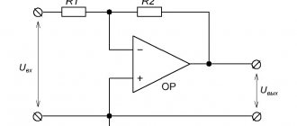
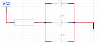
Before considering the procedure, you should understand the design features of the triac. In an electrical sense, it is a semiconductor element that, like a thyristor, can open and close to allow current to flow, but, unlike a thyristor, a triac allows current to flow in two directions. Therefore, its design contains two counter-directed crystals, which are opened and closed by a control electrode; due to this feature, it is sometimes considered a type of thyristor.
Rice. 1. Schematic diagram of a triac
Look at Figure 1; during the operation of the device, either a line break may occur with a violation of the integrity of the circuit, or a breakdown of the pn junction, characterized by a short circuit. To check a triac with a multimeter, two methods are used - with soldering the semiconductor device and on the board. The second option is more convenient, since you can check without unnecessary manipulations with radio components, however, the measurements will also be affected by the overall performance of the circuit.
Therefore, to increase accuracy, the triac is unsoldered from the board and checked, otherwise a short circuit in a parallel-connected branch will show a malfunction on the multimeter even if the test object is actually usable.
If you remove the triac
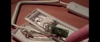
Let's consider the option of completely separating the triac from the board; as a result, you should get a completely separate independent part.
Rice. 2. Unsolder the triac
The main question that you must decide on is the location of the pins or the pinout of the legs of the part. Below are several typical models, but it should be noted that in practice a different order of alternation may occur, so you must determine the location of the control contact in relation to the two workers in advance using the model or passport of the triac.
Rice. 3. Location of triac pins
As you can see in Figure 3, in any model there will be three outputs - two power ones, which are marked A1 and A2, in some versions they designate thyristors and are marked as T1 and T2. The third leg is the control output, it is marked as G, from the English gate - gate. After you understand the design of a particular triac and the pinout of the terminals, proceed to setting up the measuring device. Most digital multimeters have a separate position for “continuity”; on the panel it is designated as a semiconductor diode.
Rice. 4. Select dialing mode
However, this is not the only option; some versions of the digital tester have a combined function, which is expressed on the panel by one mark that combines both the continuity test and the ohmmeter function:
Rice. 5. Combined ohmmeter with continuity tester
After switching, install the multimeter probes into the appropriate sockets; as a rule, to check the triac, you will need a COM connector - this is a common terminal and a connector for measuring resistance or with a continuity icon. In this mode, a potential difference will arise between the probes, since a test voltage is artificially applied to them, and accordingly, some current will flow through the triac.
Having prepared the multimeter and understood the triac device, you can proceed to the serviceability check itself.
The procedure will include several stages:
- To check whether the junction is broken, you first need to attach the tester probes to the power terminals. During the procedure, the value 0 or 1 may appear on the display, where 0 indicates a broken semiconductor, and one is fully operational. Some meter models may display the OL value instead of one, both of which indicate high resistance.
Rice. 6. Ring power contacts
- Then move one of the leads to the control pin, this will measure the resistance between them. Typically, the voltage drop between A1 and G will range from 100 to 200, but there may be some differences depending on the model. Move the probe from one power terminal of the triac to another, the value in good condition should be equal to 1.
- To check whether the triac junction opens, briefly touch the control electrode while applying voltage to the power contacts. The readings on the display will immediately change, which will indicate that the device is working properly. However, the on-state operation will most likely not last long, since the applied voltage will not be enough to produce a holding current. To connect the probe output to two legs at once, you can use either an additional wire or touch them diagonally with the probe itself.
If the soldered triac showed good results in all positions, then the problem lies in another element or node of the circuit.