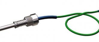
Thermocouples are the most common temperature measuring device. Thermocouples generate voltage when heated and the resulting current allows temperature measurements to be taken. It is distinguished by its simplicity, low cost, but impressive durability. Due to its advantages, thermocouples are used everywhere.
Standard thermocouple
We recommend that you pay attention to other instruments for measuring temperature.
Working principle of thermocouple
A thermocouple consists of two wires made of different metals. These two wires are bonded or welded together to form a junction. When this junction is exposed to temperature changes, the thermocouple reacts to them by generating a voltage proportional in magnitude to the temperature changes.
If a thermocouple is connected to an electrical circuit, the amount of voltage generated will be displayed on the scale of the measuring device. The meter readings can then be converted into temperature readings using a table. On some instruments the scale is calibrated directly in degrees.
Thermocouple in an electrical circuit
Thermocouple junction
Most thermocouples are designed with only one junction. However, when a thermocouple is connected to an electrical circuit, another junction may form at its connection points.
Thermocouple circuit
The circuit shown in the figure consists of three wires labeled A, B, and C. The wires are twisted together and labeled D and E. A junction is an additional junction that is formed when a thermocouple is connected to the circuit. This junction is called the free (cold) junction of the thermocouple. Junction E is the working (hot) junction. There is a measuring device in the circuit that measures the difference in voltage values at two junctions.
The two junctions are connected in such a way that their voltage opposes each other. Thus, the same voltage value is generated at both junctions and the device readings will be zero. Since there is a directly proportional relationship between temperature and the amount of voltage generated by a thermocouple junction, two junctions will generate the same voltage values when the temperature across them is the same.
Effect of heating one thermocouple junction
When the thermocouple junction heats up, the voltage increases in direct proportion. The flow of electrons from the heated junction flows through the other junction, through the measuring instrument and back to the hot junction. The device shows the voltage difference between two junctions. Voltage difference between two junctions. The voltage difference shown by the meter is converted into temperature readings, either using a table or directly displayed on a scale that is calibrated in degrees.
Thermocouple cold junction
The cold junction is often the point where the free ends of the thermocouple wires are connected to the meter.
Since the thermocouple circuit meter is actually measuring the voltage difference between the two junctions, the cold junction voltage must be kept as constant as possible. By maintaining the voltage at the cold junction at a constant level, we thereby ensure that a deviation in the readings of the measuring device indicates a change in the temperature at the working junction.
If the temperature around the cold junction changes, the voltage across the cold junction will also change. As a result, the voltage at the cold junction will change. And as a result, the difference in voltage at the two junctions will also change, which will ultimately lead to inaccurate temperature readings.
In order to keep the cold junction temperature constant, many thermocouples use compensating resistors. The resistor is in the same location as the cold junction, so the temperature affects the junction and the resistor at the same time.
Thermocouple circuit with compensating resistor
Working junction of thermocouple (hot)
A service junction is a junction that is exposed to the process whose temperature is being measured. Due to the fact that the voltage generated by a thermocouple is directly proportional to its temperature, when the working junction is heated, it generates more voltage, and when cooled, less.
Working junction and cold junction
What is a thermocouple
Thermocouples exist due to a phenomenon called contact potential difference. If two different solid conductors or semiconductors are brought into close contact with each other, then separated electrical charges are formed in the vicinity of the place of their contact. In this case, a potential difference will arise at the outer ends of these conductors. This potential difference will be equal to the difference in work functions for each metal divided by the charge of the electron.
Question to the expert
Why do you need a voltmeter when selecting a thermocouple?
It will not be possible to measure the contact potential difference with a voltmeter, but it will manifest itself in the current-voltage characteristic, for example it manifests itself in a transistor and in a diode at a pn junction.
It is clear that if you close such a pair into a ring, then the resulting emf will be equal to zero, and if on one side it is still left open, then there will be a real emf ranging from tenths of a volt to units of volts, depending on what this is for the materials.
Additional material: How to make a laboratory power supply yourself.
The point is that when, for example, two metals come into contact, the system goes out of balance because the chemical potentials of these two metals are not equal to each other, as a result, electrons diffusion towards a decrease in their energy, which in turn leads to a change in charge and electric potential of metals brought into contact. So in the near-contact region the electric field begins to grow, and as a result we have what we have.
If we now again consider these two conductors made of different metals, only closed in a ring, when the total EMF along the closed circuit becomes zero, then here we get two contact points. Let's call these places junctions. So, there are two junctions of two different conductors. What if you try to heat one of the junctions and leave the other at room temperature? Obviously, since the connected metals are different, and there is a contact potential difference at each junction, the junctions will experience different EMF deviations when they are at different temperatures.
The principle of operation of a thermocouple.
The experiment proves that the potential difference between the junctions will be proportional to the difference in their temperatures, so that a proportionality coefficient can be introduced, which is called thermo-emf. For different thermocouples, the thermo-emf will be different. If you measure the voltage in a section of such a ring, then in a certain temperature range it will turn out to be almost strictly proportional to the temperature difference between the junctions. And even if you leave only one junction (as in the figure), and only heat it up, and measure the voltage between the two ends located at the same room temperature, you can still detect a very clear dependence of the EMF on the current temperature of the junction.
What is the difference between parallel and series connection of capacitors?
Read more
Do-it-yourself pirate metal detector - detailed instructions.
Read more
What is a tuning resistor: description of the device and its scope.
Read more
This is how thermocouples work. The described phenomenon refers to thermoelectric ones, and the effect itself, on the basis of which all thermocouples operate, is called the Seebeck effect, in honor of its discoverer, Thomas Seebeck. Today you can find industrial thermocouples in which, depending on the required measured temperature range, the electrodes are made of specially selected alloys.
For example, thermocouples made of chromel and alumel alloys have a thermo-EMF coefficient of 40 microvolts per °C and are designed to measure temperatures in the range from 0 to +1100 °C. And the copper-constantan pair, so popular as a demonstration aid, allows you to measure temperatures from -185 to +300°C.
Types of Thermocouple
Thermocouples are designed to cover a range of temperatures and can be made from combinations of different metals. The combination of metals used determines the temperature range measured by the thermocouple. For this reason, letter markings have been developed to identify the different types of thermocouples. Each type is assigned a corresponding letter designation, and this letter designation indicates the combination of metals used in that thermocouple.
Types of thermocouples and their temperature range
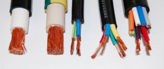
When a thermocouple is connected to an electrical circuit, it will not work normally unless the polarity of the connection is correct. The positive wires should be connected together and connected to the positive terminal of the circuit, and the negative wires to the negative terminal. If the wires are mixed up, the working junction and the cold junction will not be in antiphase and the temperature readings will be inaccurate. One way to determine the polarity of thermocouple wires is to determine the color of the insulation on the wires. Remember that the negative wire in all thermocouples is red.
Thermocouple wire insulation color
In many cases, it is necessary to use wires to extend the length of the thermocouple circuit. The color of the insulation of the connecting wires also carries information. The color of the outer insulation of the connecting wires varies depending on the manufacturer, but the color of the primary insulation of the wires usually corresponds to the coding indicated in the table above.
Features of the use of the most common thermocouples
Technical characteristics depend directly on the materials from which they are made.
Type J (Iron Constantan Thermocouple)
- It is not recommended to use below 0°C, because Moisture condensation on the iron terminal leads to the formation of rust.
- The most suitable type for rarefied atmospheres.
- The maximum temperature of use is 500°C, because Above this temperature, rapid oxidation of the leads occurs. Both terminals are quickly destroyed in a sulfur atmosphere.
- The readings increase after thermal aging.
- Low cost is also an advantage.
Type E (chromel-constantan thermocouple)
- The advantage is high sensitivity.
- Thermoelectric homogeneity of electrode materials.
- Suitable for use at low temperatures.
Type T (copper-constantan thermocouple)
- Can be used below 0°C.
- Can be used in atmospheres with slight excess or deficiency of oxygen.
- Use at temperatures above 400°C is not recommended.
- Not sensitive to high humidity.
- Both leads can be annealed to remove materials causing thermoelectric inhomogeneity.
Type K (chromel-alumel thermocouple)
- Widely used in various areas from -100°C to +1000°C (recommended limit depending on the diameter of the thermoelectrode).
- In the range from 200 to 500°C, a hysteresis effect occurs, i.e., readings during heating and cooling may differ. Sometimes the difference reaches 5°C.
- Used in a neutral atmosphere or an atmosphere with excess oxygen.
- After thermal aging, the readings decrease.
- It is not recommended to use in a rarefied atmosphere, because... chromium can be released from the Ni-Cr terminal (so-called migration), and the thermocouple changes the thermoelectric force and shows a low temperature.
- A sulfur atmosphere is harmful to a thermocouple because affects both electrodes.
Type K thermocouple.
Type N (nicrosil-nisil thermocouple)
- This is a relatively new type of thermocouple, developed from the K-type thermocouple. The K-type thermocouple can be easily contaminated by impurities at high temperatures. By fusing both electrodes with silicon, the thermocouple can be precontaminated and thus reduce the risk of further contamination during operation.
- Recommended operating temperature up to 1200°C (depending on wire diameter).
- Short-term operation is possible at 1250°C.
- High stability at temperatures from 200 to 500°C (significantly less hysteresis than for a type K thermocouple).
- Considered to be the most accurate base metal thermocouple.
General Tips for Selecting Base Metal Thermocouples
- Application temperature below zero – type E, T
- Room temperatures for use – type K, E, T
- Application temperature up to 300°C – type K
- Application temperature from 300 to 600°C – type N
- Application temperature above 600°C – type K or N
Precious metal thermocouples
- Recommended maximum operating temperature 1350°C.
- Short-term use is possible at 1600°C.
- It becomes contaminated at temperatures above 900°C with hydrogen, carbon, and metallic impurities of copper and iron. When the iron content in the platinum electrode is 0.1%, TEMF changes by more than 1 mV (100°C) at 1200°C and 1.5 mV (160°C) at 1600°C. The same picture is observed with copper contamination. Thus, thermocouples should not be reinforced with steel tube, or the electrodes should be insulated from the tube with gas-tight ceramics.
- Can be used in oxidizing atmosphere.
- At temperatures above 1000°C, the thermocouple may become contaminated with silicon, which is present in some types of protective ceramic materials. It is important to use ceramic tubes consisting of high purity aluminum oxide.
- It is not recommended to use below 400°C, since the thermoelectric force in this region is small and extremely nonlinear.
Precious metal thermocouples
Type R (platinum-rhodium-platinum)
The properties are the same as those of type S thermocouples.
It will be interesting➡ What is the electrical capacity of the capacitor?
Type B (platinum-platinum-rhodium)
- Recommended maximum operating temperature is 1500°C (depending on wire diameter).
- Short-term use is possible up to 1750°C.
- Can become contaminated at temperatures above 900°C with hydrogen, silicon, copper and iron vapor, but the effect is less than for thermocouples of types S and R.
- At temperatures above 1000°C, the thermocouple may become contaminated with silicon, which is present in some types of protective ceramic materials. It is important to use ceramic tubes consisting of high purity aluminum oxide.
- Can be used in oxidizing environments.
- Application is not recommended at temperatures below 600°C, where the emf is very small and nonlinear.
Summary table of thermocouple types.
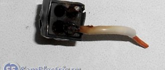
Thermocouple faults
If a thermocouple is giving inaccurate temperature readings and it has been checked that there are no loose connections, then the cause may lie either in the recording device or in the thermocouple itself, the recording device is usually checked first, since devices fail more often than thermocouples.
Moreover, if the device shows at least some readings, even if inaccurate, then most likely the problem is not the thermocouple. If the thermocouple is faulty, it will usually not produce any voltage at all and the meter will not give any readings. If there is no reading on the device at all, then the problem is probably the thermocouple.
If you suspect that the thermocouple has failed, check its output signal using a device called a millivolt potentiometer, which is used to measure small voltages.
Potentiometer