How to make an electric baby carrier with a switch
I welcome you, dear readers, to my website.
And today we will talk about how to make an electric carrier with a switch with your own hands. Agree with me that at home it is very difficult to do without an extension cord. I use this miracle of technology every day. My computer and all the other components for it are included in the carrier with a block of four sockets. However, I think it’s the same for many people. It’s unlikely that anyone at home has a place where there are three or four sockets at once.
And if the house is also undergoing renovation, then there is no way to do it without an extension cord. Since you will need to connect the power tool in any case. And if several people are doing the repairs, then carrying one socket will not be enough for them. You need to make an extension cord with several sockets at once. Because if people work in turns, it will take too much time.
You can, of course, take a simpler route, just go to any hardware store or market and buy several carriers at once. By the way, recently carriers in the form of a coil of wire wound on a reel have appeared on the market.
But such coils are not always convenient to carry with you, and besides, if you need to turn on something powerful, such as welding, then all this wire must be completely unwound from the reel.
Now imagine if you have 50 meters in a bay and all this wire is spread out around the house or apartment, or worse, in one room. It will simply be difficult for you to move without getting entangled in these networks.
Therefore, I suggest you make a carrier with your own hands using available materials. The price will be much cheaper than the store one, and the reliability will be no worse, and quite possibly even better.
Accessories for assembling an electric carrier.
In order to assemble a good and reliable carrier, you first need to decide what devices you will include in it, and calculate the total power.
But if there are no serious loads, then you can assemble the carrier using the simplest components.
Let's start with choosing a wire. If the total load of all devices does not exceed 2 kW, then for carrying you can use a wire with a cross-section of 1 mm 2. And the socket and plug must withstand a current of 10 A.
Usually the manufacturer writes on the body of their products what voltage and current they are designed for, so I advise you to pay attention to this when purchasing.
If the load is about 3 kW, then you need to take a wire with a cross-section of 1.5 mm 2. And the socket and plug must withstand a load of 16 A.
If the load is within 5 kW, then the wire must have a cross-section of at least 2.5 mm 2. But the current with such a load will be about 23 A. So you need to buy the appropriate type of plug and socket.
Now, as for the brand of wire. The fact is that carriers very often have to be twisted and untwisted, so I advise you to take only PVA wire.
The wire of this brand has a stranded core and good insulation, which makes it flexible and will last a long time. And wires with a monolithic core are not suitable for carrying.
List of materials for making the carrier yourself:
- Collapsible electrical plug (designed for the power you need);
- Socket or block of sockets (several sockets);
- Wire of the required length and appropriate cross-section;
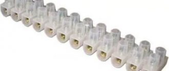
- NShVI lugs for crimping stranded wires (although if you carry small loads, you can do without lugs).
- screwdriver;
- pliers;
- press jaws;
- knife or special device for stripping insulation from wires.
Instructions for assembling a good extension cord
11.11.2014 4 comments 21
Most often, the desire to make an electrical extension cord with your own hands arises when there is an urgent need (for example, during repairs) or when you are disappointed in finished products from manufacturers. And in fact, it is not uncommon for a washing machine or other electrical appliance to be connected to a portable outlet, when the socket begins to melt and turn yellow. This is due to the fact that manufacturers skimp on cable cross-section and build quality, which entails an inability to withstand network loads. To prevent this from happening, you can make a powerful electrical extension cord yourself, spending literally half an hour and a little money. Next, readers of “Electrician Himself” will be provided with simple instructions and useful tips from our specialists!
So, first, let’s figure out what you can use to make a good electrical extension cord at home:
- Demountable electrical plug. You can cut it off from a broken electrical appliance, or you can buy a new one. The requirement for the plug is that it must be grounded.
- Three-core cable of the required length. Here you need to pay attention to the purpose of the future homemade product. If powerful electrical appliances (for example, a welding machine) will be connected, the diameter of the cores must be suitable. It is better to calculate the cable cross-section for current and power in advance. so as not to encounter problems such as socket melting and short circuit in the future. Most often, when assembling an electrical extension cord at home, PVS 3*1.5 and PVS 3*2.5 wires are used.
- A block of sockets (or just one). There are also several main requirements here: the back wall of the outlet must be closed, the product must have grounding contacts, and the design must be made dust and moisture resistant. If all these requirements are met, the issue of safety of using such an electric carrier will not worry you in the future.
As for tools, you may need the following:
- multimeter (allows you to check the extension cord after assembly);
- curved and straight screwdriver;
- pliers or a special tool for removing insulation from wires;
- sharp knife;
- insulating tape.
Using an example, let's look at how to make an electrical extension cord yourself from a three-wire cable with sockets for 4 sockets. So, the assembly instructions look like this:
- Unscrew the plug and socket block to prepare places for fixing the cores.
- Remove 4-6 cm from the top sheath of the cable on both sides.
- We strip each wire by 10 mm, as shown in the photo below.
- We insert the wires into the corresponding terminals and tighten the screws thoroughly with a screwdriver.
We twist the socket block and plug in the reverse order. If the cable dangles in the pass-through hole, wrap a little insulation to make the fit tighter. Using a multimeter, we connect a homemade electrical extension cord. If everything is correct, plug the plug directly into the power supply and use it.
That's all the instructions for creating. We hope that now you know how to make an electrical extension cord with your own hands at home. If you suddenly have any questions, ask them to our specialists in the “Question to an Electrician” category!
I would like to additionally note that it is possible to make a more reliable version of the electrical extension cord with a switch in the form of a button. In this case, you can turn off or turn on the power to the sockets. If you decide to assemble a long carrier (for example, 50 meters), then it is better to wind it on a special reel so that the wires do not constantly get tangled. In addition, a coil is more convenient to store than a coil of wires.
We also recommend watching this visual video lesson:
Video instructions for assembling a homemade extension cord
Video instructions for assembling a homemade extension cord
Now let's look at a real example of assembling a carrier.
Let’s say you need to make a carrying case, which will include a heater with a power of 1.5 kW, sometimes a drill with a power of 0.85 kW will be turned on, or some other small thing: a phone charger, a portable lamp, a soldering iron, and maybe something else. If you calculate the total power of all these devices, it will be no more than 3 kW. Based on this, I will take PVS wire 3 * 1.5 mm 2, it will be enough. There will even be a power reserve.
I’ll make a small digression and explain a little what these numbers mean - 3 * 1.5 mm 2.
3 – the first digit always indicates the number of cores in the wire. It is advisable to take a three-core wire for carrying, since in addition to phase and zero, we will also have grounding.
1.5 mm 2 is the cross-section of one core. It happens that in a wire or cable several cores have one cross-section, and one or more wires have a different cross-section.
How to make an electric baby carrier with a switch.
I have had cases where I included something in the carrier, but this device or tool did not work. And then I start looking for what is the reason - the power tool or the carrier. But if there is a backlit button installed on the socket block, then it becomes visually visible whether there is voltage in the carrier. And the search circle is significantly reduced.
So let's install a backlit button in our carrier. You can, of course, take the easier route and buy a ready-made socket block with a button in the store. But the installation process itself is important to you and me, so we will install the button ourselves.
At a hardware store we buy a backlit button KCD3. When purchasing, pay attention to the technical specifications. It is necessary that the button be designed for a voltage of at least 220 V, usually they say 250 V, the current is 16 A and the degree of protection must be no less than IP - 55.
There will be three contacts on the button. Two are needed for connecting (switching) power, and the third is for backlighting.
To install a button in our socket block, we need to cut a corresponding hole for it. To do this, you can use a drill and a small file. We drill several holes, and then use a file to adjust them to the required dimensions. The main thing is not to overdo it so that the button does not dangle in the case.
The button should be marked where the input and output are, and where the contact for the backlight is.
Now we connect the button as follows: we connect the wire from the contact terminal of the socket to the backlight contact. If you have PVA, then you need to connect the blue wire. Now, so to speak, we connect the phase conductor to the “input”, and connect the wire from the “output” to the second contact terminal of the socket.
The third wire, as you remember, sits on our grounding. Close the cover of the socket block and you can check.
If you turn on the button, it should light up, thereby signaling that there is voltage in the outlet. When you turn it off, the backlight will go out, and accordingly the sockets will not work.
Attention. With this button connection scheme, the circuit breaks on only one wire, that is, a phase may be present in the sockets. If you need to completely remove the voltage from the outlet, then you need to install two buttons. Or if you buy a block of sockets with a button already installed, then there should also be two of them.
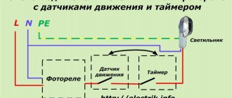
How to connect an illuminated switch?
There is no difference in the appearance of a regular switch without backlight and a switch with backlight, except for the backlight window. The backlight only works when the lighting is turned off, and does not consume much electricity. The backlit switch circuit is assembled using a resistor with a neon lamp and a resistor with an LED.
When the switch is off, voltage is supplied to the indication through the filament of the lamp, which has low resistance. The indicator lights up because almost 220 V is applied to it. If the switch is turned on, the contacts of the indicator lamp are short-circuited, the current goes directly to the incandescent lamp, the backlight does not light up.
Connecting an illuminated switch
A question may arise. Why is the backlight on, but the lamp is not lit? The current through the backlight, whether neon or LED, is limited by high resistance, so it is not enough to light an incandescent lamp. An incandescent lamp requires a large current.
Connecting the backlight to the switch contacts
The backlit switch connection diagram can be assembled using a neon light bulb or LED with a resistor. Illuminated switches assembled with LEDs may not always work well with fluorescent and LED lamps. The indicator light may be so small that it may not be noticed.
This is explained by the fact that the resistance of the power supply of energy-saving and LED lamps is greater than the filaments of incandescent lamps. The current is limited by this resistance, and the voltage on the indicator is not enough to illuminate the switch.
Schemes of backlit switches assembled on LEDs
Below is a simple diagram of a backlit switch, assembled on one LED and can be easily repeated.
The first diagram for connecting LED backlight to a switch
The purpose of the VD1 diode according to the circuit is protection against breakdown of the LED by reverse voltage. The reverse voltage of the LED is 20 V, and the reverse voltage in the network for it is equal to the value of the negative part of the sine wave, which is significantly higher than Urev of the LED. This LED switch circuit consumes up to 1 kW of electricity per month, which is quite a lot.
If you want to assemble this or another lighting circuit, the connections must be twisted and soldered. Exposed wires and resistors must be well insulated with electrical tape or heat shrink tubing. Another backlight circuit using a resistor and capacitor.
The second diagram for connecting the LED backlight to the switch
The capacitor here plays the role of a voltage divider. The resistor in this circuit is set to 100 - 500 ohms, it is designed to limit the charging current of the capacitor. Electricity consumption in this backlight scheme is less than 50 W per month. The disadvantages of LED circuits include their size. However, there is enough space in the switch body.
Neon light circuit using a resistor
The illumination on a neon lamp is small in size and consumes little electricity. A neon bulb requires very little current to light, making it suitable for energy-saving lamps and for illuminating LED switches.
The neon lighting circuit is suitable for energy-saving and LED lamps
The resistor is selected with a power greater than 0.25 W. A neon light bulb is not difficult to find in your home. They are used as voltage indicators in extension cords, electric kettles, irons and other household electrical appliances. Such indicators are already completely ready for installation in switches.
Interesting articles too
How to choose sockets and switches
Connecting an rj 45 socket. How to connect an internet socket
Socket in the bathroom. Requirements for sockets in the bathroom
Connecting a single-key switch
Surge filter button - review and repair
A surge protector is a useful device that protects sensitive electrical appliances from power surges and impulse noise.
Externally, a household filter resembles a regular extension cord, but it is additionally equipped with a built-in unit that absorbs all frequency fluctuations.
To protect against large surges, the device is equipped with a fuse, which in case of critical overloads instantly disconnects electrical appliances from the network.
Like any other devices, surge protectors can break down during intensive use.
One of the most common reasons for the failure of a surge protector is a breakdown of the on-off button, or rather, burning of the contacts inside this button.
First, when turned on, it begins to spark, heat up and make strange sounds, and over time it stops working altogether. If the filter is used frequently, the button may wear out physically or become mechanically damaged.
Attention! If the surge protector button begins to spark, heat up and/or crackle, further operation of the device is unsafe! You should immediately disconnect the filter from the mains to avoid fire! For safe operation of the filter, you need to check the condition of the switch contacts and, if necessary, clean them of carbon deposits.
Let's look at the button diagram of a typical surge protector:
As can be seen from this diagram, there is nothing complicated in the design of the surge protector power button , so you can repair it or replace it with a new one yourself.
Making an extension cord: step-by-step instructions
As a rule, the manufacturing process does not take much time, so if you have all the necessary elements and tools, you can make an electrical extension cord in 15 - 20 minutes. To do this, follow these steps:
- Disassemble the fork; as a rule, it is unscrewed with one or more bolts, but the design may differ in different models.
Rice. 1: Disassemble the plug - Cut the electrical cable; to do this, remove the required length from the point where it is connected to the plug contacts to the point where the extension cord exits the plug. It should be noted that at the exit point the cable must have both layers of insulation, so you should not strip the top layer of dielectric with a margin.
Figure 2. cut the cable - Prepare a wire to connect to the plug terminals. To do this, step back about 1 - 2 cm from the edge of each core and carefully trim the rubber insulation.
Rice. 3. Strip the ends
Be careful not to cut the core wire, otherwise this will reduce the cross-section and may lead to further overheating at the attachment point.
- Depending on the method of fastening in the plug contacts, prepare the ends of the wire (make loops, twist into one core, etc.).
- Do all these procedures for the second end of the wire.
- Connect the ends of the wire to the ends of the plug and assemble it.
Figure 4: Connect the wire to the plug terminal
Please note that the assembled fork should not have any gaps - both parts fit snugly against each other. If you find a gap, disassemble it again and eliminate the cause of the unevenness. Where it exits the plug, the extension cord should fit snugly against the edges; if its diameter is not enough, add a little electrical tape.
As a standard, they are equipped with one bolt in the center of the socket, but if the cover does not budge, you should inspect the structure for the presence of additional fastening points.
Rice. 7: standard socket mounting point
- Connect the ends of the wires to the corresponding outlet terminals of the electrical extension cord.
Rice. 8: Connect the wire to the socket terminals
If you are making a device for a three-wire network, be sure to follow the wire markings. Especially for the ground wire, otherwise you may apply voltage to the body of the device.
- Reassemble the socket in reverse order, the electrical extension cord is ready.
Rice. 9: assemble the socket - the extension cord is ready
Please note that when connecting certain parts, contact must be ensured using special clamps, sleeves or by soldering. It is under no circumstances allowed to ensure contact only by screwing the wire to the lamellas or other parts. After making an electrical extension cord, do not rush to plug it into the outlet; first check its serviceability using a multimeter.
Checking the serviceability of the electrical extension cord.
To check the functionality of the carrier, you will need a regular multimeter or megohmmeter. The whole process can be divided into checking the integrity of the line and checking the insulation. Initially set the multimeter to dialing mode:
- Connect one lead of the multimeter to the socket of the outlet, and touch the second lead to the plug of the electrical extension cord. If the device does not report a circuit, touch the second prong of the plug.
- Hold the multimeter probe on the same contact of the plug where the device showed the circuit, and check other sockets in the block. Their contacts of the same name should also provide a circuit for the continuity of the electrical extension cord.
- Check the second pair of contacts of the electrical sockets and the output of the extension plug; they should also show the presence of a continuity circuit.
- If you are using a three-wire extension cord, make the same connection between the grounding pins on the plug and each outlet.
Rice. 10: principle of continuity of the extension cord
The presence of a circuit between all of the listed terminals indicates that the extension cord can normally transmit electricity in a closed circuit. But, in addition to the circuit, it is necessary to ensure the condition of the insulation. What is a megohmmeter used for? But if you don’t have one, you can use the same multimeter in insulation measurement mode. For industrial purposes, measuring insulation with a multimeter is not permissible, but for domestic needs this will be quite sufficient.
During the measurement process, you need to set a limit on the maximum resistance value in kOhms or MOhms. Apply the probes to the phase and zero terminals on the plug; if the resistance is more than 500 MOhm or infinity, its level is sufficient for normal operation of the electrical extension cord.
Rice. 11: measurement of resistance between phase and zero
If the resistance approaches zero or is tens of ohms, you have broken the insulation somewhere and you need to double-check all electrical contacts in the extension cord. If there is a grounding contact, the resistance value must also be checked between phase - ground and between zero - ground.
Rice. 12: ground resistance measurement
If during testing you have determined the integrity of the phase, zero and ground circuits in the manufactured electrical extension cord, as well as a sufficient level of resistance between all terminals, then such a carrier can be safely used to connect equipment.
A surge protector is a useful device that protects sensitive electrical appliances from power surges and impulse noise.
Externally, a household filter resembles a regular extension cord, but it is additionally equipped with a built-in unit that absorbs all frequency fluctuations.
To protect against large surges, the device is equipped with a fuse, which in case of critical overloads instantly disconnects electrical appliances from the network.
Like any other devices, surge protectors can break down during intensive use.
One of the most common reasons for the failure of a surge protector is a breakdown of the on-off button, or rather, burning of the contacts inside this button.
First, when turned on, it begins to spark, heat up and make strange sounds, and over time it stops working altogether. If the filter is used frequently, the button may wear out physically or become mechanically damaged.
Attention! If the surge protector button begins to spark, heat up and/or crackle, further operation of the device is unsafe! You should immediately disconnect the filter from the mains to avoid fire! For safe operation of the filter, you need to check the condition of the switch contacts and, if necessary, clean them of carbon deposits.
Let's look at the button diagram of a typical surge protector:
As can be seen from this diagram, there is nothing complicated in the design of the surge protector power button , so you can repair it or replace it with a new one yourself.
Repair - what to do if the surge protector button is broken
If, when you turn on the surge protector button, extraneous sounds begin to be heard, which are accompanied by the smell of melting plastic, the device should be immediately de-energized. Next, you need to disassemble the surge protector and check the condition of the contacts on the switch.
To do this you will need the following tools:
- soldering iron,
- crosshead screwdriver,
- tester,
- sandpaper-zero.
If the contacts are burnt out, the tester readings will confirm this (in this case, there will be no voltage at the output from the button in the “On” position). To clean the contacts, the switch needs:
- Disassemble the surge protector housing by unscrewing the mounting screws;
- Unsolder the button and remove it from the filter housing. The button is held in the housing by plastic clips, which should be carefully squeezed out.
- Disassemble. To do this, you need to disconnect the key by picking it up with a flat-head screwdriver.
- Take out the contacts and clean off any black deposits.
- Assemble the button. After this, we assemble the button in the reverse order, install it in place and solder it.
If the contacts have burned very badly and melted the plastic of the switch housing, it should be completely replaced.
To do this you need:
- Disassemble the filter;
- Unsolder the button;
- Remove the switch from the housing;
- Install a new one in its place (sold in radio parts stores, costs about 30 rubles);
- Solder the button and assemble the filter housing.
Often the button on the surge protector does not work due to mechanical damage. The most common case is the breakdown of the latches that hold the switch key in the housing. In this case, it is not necessary to buy a new button - the latches can be restored.
To do this you will need the following materials and tools:
- screwdriver (or drill) and drill with a diameter of 3.5 mm;
- toothpick;
- cotton swab;
- side cutters.
The process itself is very simple:
- A through hole is drilled in the key into which a cotton swab is inserted (it will act as a latch).
- A toothpick is inserted inside the cotton swab for greater rigidity. On both sides, the improvised retainer is trimmed with side cutters so that on each side it protrudes approximately 3-4 mm.
- Now all that remains is to insert the key into the body - to do this, just slightly bend the sides of the seat with a screwdriver.
VIDEO INSTRUCTIONS ” alt=””>
Triple socket: preparing for installation
The installation of a triple socket has its own specifics depending on the hidden or open routing of wires. Hidden or internal wiring requires more careful and lengthy preparation. First of all, you should clarify the ability of the product to withstand triple loads. Otherwise, as a result of overheating, the burnt wires will have to be replaced.
The installation location is also marked in advance, maintaining the general level for future components of the outlet. The height from the floor is the same as for single devices.
The centers of the rosettes are marked in the same way, the dimensions are laid to the right and left of the central product. In some cases, marking may start from the outermost device.
If possible, in order not to lay new wiring, it is recommended to install a triple socket in place of a single device. If the wires still need to be laid, their locations are marked with horizontal and vertical lines, and then transferred to the home wiring diagram.
How to make a surge protector directly, without a button
If the old button has completely failed and you don’t have a new one at hand, you can connect the surge protector directly, turning it into a regular extension cord.
To do this you need to do the following:
- Open the mains voltage filter housing by unscrewing the mounting screws with a screwdriver;
- Unsolder the wires from the button and solder them according to color, bypassing the button;
- Insulate the joint with insulating tape or heat shrink;
- Assemble the extension cord and test its functionality.
To avoid the surge protector switch problems described in this article, consider the maximum power rating of the connected load and the maximum load current when selecting a device.
VIDEO REVIEW ” alt=””> If the total power of the equipment exceeds the maximum permissible filter power, then you should opt for a more powerful model.
How to make an extension cord with your own hands
In everyday life, situations quite often arise when the available sockets in an apartment or private house do not allow the use of any electrical appliances or household appliances. The main reason is their inconvenient location, so owners prefer to use an extension cord. In some cases, increased power outlets or a longer cord are required. In this case, home craftsmen make an extension cord with their own hands. A self-made extension cord will be much cheaper than a branded one and much more reliable. If you have the skills to work with the tool, the entire procedure takes from 15 minutes to half an hour.
Preparing to assemble the extension cord
Before making an extension cord, you first need to decide on its purpose. This will allow you to determine the possibility of connecting certain devices, as well as the maximum permissible power. These factors have a direct impact on the choice of cable cross-section and other components. It is recommended to select all parameters with a small margin, so that in the future there is the possibility of connecting more powerful electrical equipment.
First of all, you need to buy a wire that will be used as a cord. The best option is considered to be PVS copper wire, which is characterized by increased flexibility. If there is a grounding contact in the socket, the wire must be three-core, but if it is absent, a cable with two cores can be used. When purchasing, you should carefully study the product labeling.
If the brand “PVA 3 x 1.5” is indicated, this means that the wire is three-core and the core cross-section is 1.5 mm. These parameters allow you to connect a load with a power of up to 3.5 kW. For a power of 5 kW, a cross-section of 2.5 mm will be required. The data for calculations can be taken in a special table, which will significantly speed up the solution to the question of how to make an extension cord with your own hands.
When choosing a cross-section, it is necessary to take into account the conductor length factor. For example, if the cable length is more than 100 meters, then during operation there may be a voltage drop due to the connection of high-power devices. Therefore, it is recommended to choose a cable with a larger cross-section than that provided in the calculation table.
Then you need to choose the right electrical plug, which should be removable. It is not recommended to purchase Euro-type products if you plan in advance to use sockets of an old design. Otherwise, you will additionally need an adapter. On the body of each plug there is a marking indicating the maximum current. For example, at 16A you will need a cable with a cross-section of 1.5 mm, and for 25A the cross-section will be 2.5 mm. If there is a ground connection, the plug must have a grounding pin in its design.
It is not recommended to choose a single outlet. The socket block should be at least double, and preferably with three or four elements. When choosing, you need to be very careful so as not to accidentally buy an overhead structure designed for use with open wiring. It does not have a special clamp that protects against accidental pulling out, and over time the back cover of such sockets falls out. For extension cords, there are separate options in the form of socket strips or cable sockets. If you need to connect a computer or other office equipment, then in this case a surge protector is made, which has a push-button switch and light indication.
After all the materials are prepared, you can begin assembling the extension cord. This procedure is carried out using a knife, screwdriver and pliers.
New site
Sources:
- Article
- Video
Most often, the desire to make an electrical extension cord with your own hands arises when there is an urgent need (for example, during repairs) or when you are disappointed in finished products from manufacturers. And in fact, it is not uncommon for a washing machine or other electrical appliance to be connected to a portable outlet, when the socket begins to melt and turn yellow. This is due to the fact that manufacturers skimp on cable cross-section and build quality, which entails an inability to withstand network loads. To prevent this from happening, you can make a powerful electrical extension cord yourself, spending literally half an hour and a little money. Further to the readers "
The electrician himself
» simple instructions and useful tips from our specialists will be provided!
So, first, let’s figure out what you can use to make a good electrical extension cord at home:
- Demountable electrical plug. You can cut it off from a broken electrical appliance, or you can buy a new one. The requirement for the plug is that it must be grounded.
- Three-core cable of the required length. Here you need to pay attention to the purpose of the future homemade product. If powerful electrical appliances (for example, a welding machine) will be connected, the diameter of the cores must be suitable. It is better to calculate the cable cross-section in terms of current and power in advance, so that in the future you do not encounter problems such as melting of the socket and short circuit. Most often, when assembling an electrical extension cord at home, PVS 3*1.5 and PVS 3*2.5 wires are used.
- A block of sockets (or just one). There are also several main requirements here: the back wall of the outlet must be closed, the product must have grounding contacts, and the design must be made dust and moisture resistant. If all these requirements are met, the issue of safety of using such an electric carrier will not worry you in the future.
As for tools, you may need the following:
- multimeter (allows you to check the extension cord after assembly);
- curved and straight screwdriver;
- pliers or a special tool for removing insulation from wires;
- sharp knife;
- insulating tape.
Using an example, let's look at how to make an electrical extension cord yourself from a three-wire cable with sockets for 4 sockets. So, the assembly instructions look like this:
- Unscrew the plug and socket block to prepare places for fixing the cores.
- Remove 4-6 cm from the top sheath of the cable on both sides.
- We strip each wire by 10 mm, as shown in the photo below.
- We insert the wires into the corresponding terminals and tighten the screws thoroughly with a screwdriver.
- We twist the socket block and plug in the reverse order. If the cable dangles in the pass-through hole, wrap a little insulation to make the fit tighter.
- Using a multimeter, we connect a homemade electrical extension cord. If everything is correct, plug the plug directly into the power supply and use it.
That's all the instructions for creating. We hope that now you know how to make an electrical extension cord with your own hands at home. If you suddenly have any questions, ask them to our specialists in the “Questions to an Electrician” category!
I would like to additionally note that it is possible to make a more reliable version of the electrical extension cord with a switch in the form of a button. In this case, you can turn off or turn on the power to the sockets. If you decide to assemble a long carrier (for example, 50 meters), then it is better to wind it on a special reel so that the wires do not constantly get tangled. In addition, a coil is more convenient to store than a coil of wires.
We also recommend watching this visual video lesson:
Video instructions for assembling a homemade extension cord
We recommend that you read the article: why the socket sparks when you turn on the plug!
Video instructions for assembling a homemade extension cord
How to assemble an electrical extension cord with your own hands
At the first stage, the top insulating layer is removed from both sides of the cable by approximately 5-7 cm, after which the ends of each core are stripped to 1 cm. Next, the plug is disassembled by unscrewing the fastening bolt. After this, you need to loosen the screws on the clamp that secures the cable inside the plug body. Then the stripped wires are connected to the two plug contacts.
The location of the conductors does not matter; the most important thing is to correctly connect the grounding contacts on sockets and plugs. After connecting the conductors, the plug is reassembled.
At the final stage, the socket block is disassembled and two conductor cores are connected to the contacts. The third wire is connected to the ground pin, exactly the same as on the plug. Thus, both ground contacts are connected by a single wire.
If the core consists of many wires, then it is recommended to solder it or fix it with a tip. As a last resort, you can simply twist the wires using pliers. After all connections, the cable is fixed inside the housing and the final assembly of the unit is performed. The finished extension cord is checked by plugging it into a home electrical outlet or using a multimeter.
Advantages of use
Thanks to this design, you can save on electrical wiring installation, since the work is concentrated in one place.
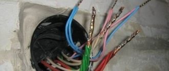
No external damage - scratches, cracks, chips. The wires of the new wiring are connected to the junction box, their ends are securely insulated with special caps.
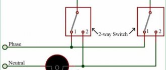
Using a three-key switch with a socket will be justified if your home has exposed electrical wiring. Multi-level ceilings, arches, niches require separate lighting. These two wires must be connected alternately with all the wires being tested.
A three-button switch can turn on a three-light chandelier as a whole, but only all the bulbs together or separately, as you wish. The circuit can also work when a neutral wire is installed on the switch, but it is more correct and safer to install it on a phase in the break. Otherwise, the light fixture will always remain energized, creating a risk of electric shock when replacing bulbs. The input phase L is connected from the single terminal side, and the output phase L1.
More on the topic: How to create an estimate for electrical wiring
Device and circuit
On the other hand, a three-key switch allows you to make your home much more comfortable. With its help, you can divide your room into several illuminated zones. The edge of the key is pressed against the wall with your finger in the off position, the other, protruding edge is picked up with a fingernail or a flat screwdriver and pulled towards itself. The other three wires went to the three switch terminals located opposite the common contact at one end, and each wire went to the phase terminal of its lighting fixture of one of the three at the other end of the cable.
We connect the wires to the junction box. We install the switch and socket in the niches. Scope of application Connection diagram Scope of application Triple switches are used in cases where it is necessary to divide lighting into different groups or rooms. However, the restrictions imposed by a standardized electrical wiring network in apartments force the use of switches with a limited number of switching sections in the control mechanism. Arriving at the switch, the phase enters its lower input contact and remains permanently on this contact.
Triple switch connection diagram
Selection criteria With all the variety of switches on the market, it is recommended to adhere to certain points: Models with self-clamping terminals. The cross-sectional area of each cable core must be at least 0.75 mm2. Triple switch: connection diagram to the chandelier L - phase to the red switch; then the phase yellow, brown, pink goes to three groups of chandelier lamps; N - blue working zero, goes directly to the chandelier and is routed by the chandelier terminal block into groups; PE - yellow-green grounding, connected to the chandelier body Thus, before connecting the triple switch, it is necessary to prepare all the wiring.
The edge of the key is pressed against the wall with your finger in the off position, the other, protruding edge is picked up with a fingernail or a flat screwdriver and pulled towards itself. For example, in the hallway you can install a triple model to turn on the lights in the kitchen, bathroom and toilet, or instead of the kitchen in the hallway itself. The remaining five are taken up by the connection process. How to connect a two-key switch
How to properly use a homemade extension cord
When using a homemade extension cord, several mandatory requirements must be met.
- There should not be any damage on the cable, and if it does appear, it must be insulated. Isolation is performed when the extension cord is unplugged from the outlet.
- If a plug or socket fails, it must be replaced. They should be protected from moisture and avoid excessive overloads.
- When operating at maximum loads, the cable must be completely unwound to avoid overheating.
{SOURCE}