Example of calculation of a centrally compressed concrete column
Given:
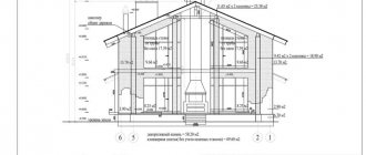
A two-story house of 8.6x12.6 m is being built. A significant open space is planned on the ground floor, for which a column with a cross-section of 40x40 cm and a height of 2.6 meters will be installed in the middle of the house. The column will be supported by a floor beam 40x30 cm, on the floor beam - hollow-core floor slabs 6 m long, a second-floor wall made of solid brick, a 2nd floor floor made of the same hollow-core slabs and a roof structure (waved asbestos-cement slate on wooden rafters):
Figure 284.1 . Plan of the first floor of a two-story house with a column in the middle.
Required:
Check the adequacy of the structural reinforcement of the column.
Solution:
1.1.
For structural reasons, class B15 concrete is accepted for the column, design compressive resistance Rb = 86.5 kgf/cm2, longitudinal reinforcement with rods d=12 mm of class A400 reinforcement, design resistance Rs = 3600 kgf/cm2, and transverse reinforcement with knitted wire clamps d=6 mm of A240 reinforcement with a distance between clamps of 15d = 15·12 = 180 mm, the thickness of the protective layer is taken to be 40 mm to ensure better adhesion of the reinforcement and concrete when concreting at home.
1.2. Collection of loads on a column
To check a column for strength and stability, you need to know what loads will be applied to the column. There will be at least 2 types of loads: permanent - from the weight of structures, and temporary, from furniture, engineering equipment, guests celebrating the New Year, snow lying on the roof, etc. Temporary loads are divided into long-term and short-term according to the duration of their action. Thus, the load on a column from snow lying on the roof may be short-term, and a New Year's feast that lasts for a couple of weeks can be considered as a long-term load, but all this matters in, let's say, professional calculations, when the main design task comes down to the maximum possible savings materials. For a single structure, saving 0.5-2% of materials does not play a big role, but the reliability of the calculated structure is much more important. Therefore, in this case, you can ignore the difference between short-term and long-term loads, and consider a certain general maximum load.
In addition, it is necessary to take into account that if the floor beam resting on the column is continuous, and therefore statically indeterminate, then the support reaction on the middle support - the column - will not be equal to ql.
First, we determine the value of the distributed loads acting on the beam.
Since the weight of a square meter of hollow core slabs is up to 350 kg, the load from the hollow core slabs of the 1st and 2nd floors will be 350x6x2 = 4200 kg/m.
The temporary load on the floor of the 1st floor will be 400x6 = 2400 kg/m, the load from the insulation of the floor of the 2nd floor will be taken equal to 200x6 = 1200 kg/m.
The load from the weight of a wall made of solid brick of the second floor with a thickness of 38 cm plus plaster on both sides with a total thickness of 3 cm, a height of 3 m will be 1800x0.41x3 = 2214 kg/m.
The temporary load from snow (for Moscow) will be 180x6 = 1080 kg/m.
The load from the self-weight of a floor beam with a cross section of 30x40 cm will be 2500x0.3x0.4 = 300 kg/m.
The load from the own weight of 2/3 of the column will be 2500x0.4x0.4x2.6x2/3 = 693 kg
The load from the roof structure will be approximately 50x6 = 300 kg/m. Approximately because the load from slate, sheathing and rafters will be about 35 kg/m, and there will also be racks, struts, and mauerlats.
Thus, the total uniformly distributed load on the floor beam will be
q = 4200 + 2400 + 1200 + 2214 + 1080 + 300 + 300 = 11694 kg/m
For reliability, we multiply the resulting value by the reliability safety factor γ = 1.2, then the calculated load will be 11694x1.2 = 14032.8 kg/m, round this value to the nearest integer to simplify the calculations. Thus, the design load will be 14,000 kg/m.
Note : the designs of walls, ceilings and roofs are accepted very conditionally.
The support reaction for a two-span beam with equal spans and a uniformly distributed load is 10ql/8 = 10x14000x4/8 = 70,000 kg or 70 tons. This support reaction will be the design load N for our column.
1.3.
It would seem that now checking the strength of the column is a piece of cake. The load divided by the area of the column must be less than the design compressive strength of the concrete. In our case
N/F = 70000/(40×40) = 43.75 < Rbγb3γd = 86.5 0.85 0.9 = 66.17 kgf/cm2
where F is the cross-sectional area of the column, γb3 = 0.85 is the coefficient of operating conditions for heavy concrete, taking into account the concreting of vertical elements with a height of more than 1.5 m (according to SNiP 2.01.03-84). γd = 0.9 is a coefficient that takes into account concreting at home (the value of this coefficient is not regulated by SNiP and therefore can not be used. However, such a coefficient seems quite appropriate to me, therefore, the less confidence in compliance with technological requirements, the lower the value of this coefficient will be. In case of complete lack of experience in concrete work, the coefficient should be taken up to γd = 0.5).
1.4.
However, there is one big and fat but .
Concrete and reinforced concrete elements are never considered as centrally compressed, but only as eccentrically compressed
In particular, because concrete is a very heterogeneous material in which the center of gravity of even a simple square section rarely coincides with the geometric center of gravity. This happens at least because the coarse aggregate - crushed stone or gravel has different sizes and sometimes different densities, in addition to this, the fine aggregate - sand often has a different density from the coarse aggregate. Even during the chemical reaction of mixing the binder (cement) with water, air bubbles can form and such bubbles will also be unevenly distributed. This means that for such sections the applied load should be considered as eccentrically applied. And such a load creates an additional moment M = eN , where e is the eccentricity of the load application. In this case, the eccentricity will be random and its value will be different for different cross sections along the length of the column, therefore, when determining the strength, the maximum possible eccentricity value should be used. Well, if the concrete mixture was poorly compacted, then the displacement of the center of gravity and, accordingly, the eccentricity value will be even greater. It is clear that theoretically calculating the maximum value of eccentricity is quite difficult, and there is no great need for it. Extensive experience in the design of concrete and reinforced concrete structures makes it possible to quite simply determine the value of random eccentricity based on the geometry of the columns.
The value of random eccentricity ea according to the requirements of the above SNiP and SP should be taken no less than:
— lо/600, where lо is the design length of the column; in our case, the column will be installed on the foundation without corresponding anchors and the floor beam will rest on the column, relatively speaking, hingedly, so the column can be considered as hinged on supports and the estimated length of the column will be equal to the length of the column. Then ea = 260/600 = 0.43 cm.
— b/30 or h/30, where b and h are the width and height of the cross section; Our cross section is square, so ea = 40/30 = 1.333 cm.
- 1 cm.
— In addition, for a structure formed from prefabricated elements, the possible disruption of the geometry of the prefabricated elements and displacement during installation should be taken into account. If the column is concreted in several stages and the formwork is installed with large tolerances, then eccentricity will also appear, and even a small displacement of the floor beam will also give eccentricity in the application of the load. Among other things, the deviation of the column from the vertical will also give eccentricity, and the lower the section of the column under consideration is located, the greater the eccentricity value will be.
Taking into account the above factors, we will take the value of random eccentricity ea = 2 cm.
Note : if in doubt, the value of random eccentricity can be taken even higher.
1.5.
But that's not all. When the element is flexible λi = lo/i >14 (or λh = lo/h > 4 for a square section), the effect of deflection on the load-bearing capacity must be taken into account. In our case, the flexibility of the column is λi = 260/(h2/12)0.5 = 22.5, λh = 260/40 = 6.5, which means that the influence of deflection will have to be taken into account.
For elements of square or rectangular cross-section, made of concrete of class no higher than B20, and having a design length lo < 20 h (in our case lo = 260 < 20x40 = 800), it is allowed to carry out calculations taking into account deflection using the following formula:
N ≤ anRbF (284.1.1)
where аn is determined according to graph 1 depending on the values of ео/h and λ = lo/h:
Schedule 1 . Determination of the value of an for eccentrically compressed concrete elements (according to SP 52-101-2003)
The value аn is determined along the solid line if the ratio M1l/M1 = 1, along the dotted line if the ratio М1l/M1 = 0.5, respectively, for other values of the ratio interpolation is used. Here M1l is the moment from constant and long-term loads, M1 is the moment from all loads. Since we do not make a difference between short-term and long-term loads, our line is solid.
At ea = eo the ratio eo/h = 2/40 = 0.05, at λ = 6.5 the value of an will be approximately 0.88, then for a cross section located at 2/3 of the column height
0.88x66.17x40x40 = 93167 kg > N = 70000 + 693 = 70700 kg
As we can see, the strength and stability of the column is ensured with a good margin, even without taking into account the operation of the reinforcement. If desired, you can reduce the cross-section of the column. For example, if the column has a cross-section of 30x30 cm, then eo/h = 2/30 = 0.0667, λ = 260/30 = 8.667, 20h = 20×30 = 600 > 260, an = 0.84
0.84x66.17x30x30 = 50425.2 < N = 70000 + 2500x0.3x0.3x2.6x2/3 = 70400 kg
and in this case the presence of reinforcement should be taken into account. To do this, we use the following formula:
N ≤ an(RbF + RscFs,tot) (284.1.2)
where Fs,tot is the cross-sectional area of the entire reinforcement, then
0.84(66.17(900 - 4.52) + 3600x4.52) = 0.84(59253.9 + 16272) = 63441.7 < N = 70400 kg
where 4.52 is the cross-sectional area of 4 reinforcement bars with a diameter of 12 mm, adopted structurally.
Since the cross-sectional area of the reinforcement adopted structurally is not enough, the required cross-section should be determined by calculation. According to formula (284.1.2)
Fs,tot = (N - anRbF)/anRsc = (70400 - 0.84×59253.9)/(0.84×3600) = 6.82 cm2
According to the table, for longitudinal reinforcement we take 4 rods with a diameter of 16 mm with a total area of 8.04 cm2.
Note : in general, formula (284.1.2) is recommended to be used when the eccentricity value does not exceed those specified in paragraph 1.4, and a different coefficient is used, however, we should not forget that we accepted the eccentricity value with a large margin and therefore for simplified For calculations, such use of the formula is quite acceptable.
However, we will soon learn how to correctly calculate the cross-section of columns for relatively large eccentricity values.
Foundation for a metal column
Monolithic glass-type foundations
Uniform distribution of loads in the frame structures of buildings and structures on the underlying soils is necessary for the stability of the entire structure, therefore it is important to correctly calculate and install the foundation for the columns, which ensures long-term operation of the walls and ceilings. Columns are often used as loaded elements in the construction of not only industrial but also residential buildings and are installed with the same stringent requirements for reliability and permissible deviations from the design calculations, regardless of the method of their production and installation.
Significant foundation requirements
In standard construction, frame buildings are erected only for industrial purposes. With the development of the segment of individual buildings consisting of several floors of a large area, load-bearing supports in the form of columns have become in demand both in the houses themselves and in adjacent structures (balconies, fences, canopies, garages for several cars).
Often the frame structure of external walls and floor support is made in the form of pillars made of reinforced monolith with the gap between them filled with light aerated concrete blocks. Uneven settlement of concrete pillars will lead to cracking of the wall material. Therefore, it is necessary to responsibly approach the correct construction of the foundation under the load-bearing elements, which are made in the form of pillars.
The main document for such construction will be the “Guidelines for the design of foundations on natural foundations for columns of buildings and structures of industrial enterprises.”
Ready-made reinforced concrete products
When designing the supporting part of a structure, standard factory-produced elements with already known characteristics and mounting loops for quick installation can be taken into account.
The base for the column is selected based on the results of studies of the mechanical and dynamic characteristics of the underlying soils. The variety of options for the general design of foundations for columns is determined by the design features, area and shape of the future structure.
Initial conditions
The dimensions of the sole for the standing support are chosen so that the load on the plane of contact with the ground does not exceed its load-bearing capacity. Typical indicators for shrinkage of each individual loaded element in the foundation did not exceed the permissible values specified in the standards.
The column can stand on a separate foundation or be located in a group for which there is a single base (strip or slab type).
Group of columns on a single base
Releases of reinforcement for future columns in a monolithic concrete slab.
When calculating a columnar foundation for a column, the area of the base of 1 column is taken as the starting value. The required number of such supports must be taken with a margin of at least 50% in strength for each element being installed.
The materials for the manufacture of single foundations are:
- reinforced concrete products;
- rubble stone;
- brick;
- poured concrete.
Rigid types of foundations include structures made of monolithic branded concrete and made of brickwork.
Columns installed on a prepared foundation differ in the type of material they are made of: metal, reinforced concrete products. Each variety has its own method of attachment at the lowest point. Column supports for them are manufactured in the factory (standard type) or directly at the construction site at the installation site (design calculation).
The monolithic self-fabrication method has the advantage that it is universal, regardless of whether the steel or reinforced concrete product will be mounted on top of the base.
Soles for reinforced concrete
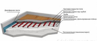
Load-bearing structures made of columns are installed on free-standing glass-type foundations, so as not to pour a large volume of concrete into strips or slabs. They will accept and distribute the load from the structure at the most critical points. Standard products for standard construction of industrial facilities are made in factories in a form ready for assembly. They consist of a sole that widens towards the bottom under the column and a column inserted into the glass.
Such prefabricated elements must comply with GOST 24476-80.
An example of a finished foundation (with various dimensions) for a column is shown in the drawing:
Increasing the area of contact with the ground due to the expanding support heel leads to the following results:
- the bearing capacity of the column increases;
- the load on the ground from the total weight of the foundation structure is reduced due to the difference in the cross-section of the base and vertical pillars - their Ø is calculated according to their ability to support the building, but does not depend on the area of support.
Example of calculation of an eccentrically compressed concrete column
The same column we are considering at different stages of construction and operation can be considered as eccentrically compressed. For example, in winter, snow can be carried by the wind from one slope to another, which will lead to a decrease in the load on one slope and an increase in the load on the other slope, this will lead to some eccentricity in the application of the load. Also, in different rooms there may be different loads on the floor, which will also lead to the appearance of eccentricity. However, with the calculation scheme we have chosen, the value of the eccentricity will not be so large, and in order not to tinker for a long time with all sorts of combinations of loads leading to the appearance of eccentricity, we adopted a safety factor for loads γ = 1.2 .
However, if during the construction process the floor slabs are laid first on the right side of the house, and then on the left (or vice versa), then after laying the slabs on one of the parts of the house, the load from these slabs will be applied eccentrically. The value of such a load will be 350x6/2 = 1050 kg/m. If the hollow core slabs were absolutely rigid, then the eccentricity value would be about 10 cm. However, both the floor beam and the slabs have some rigidity and, accordingly, the slabs will have some (albeit very small) deflection under the influence of their own weight, and also the mortar, on which slabs will be laid may not evenly transfer the load and therefore, for reliability, it is better to take a larger eccentricity value.
In order not to deal with the rather complex calculation of the nature of the load redistribution on the support platform, which in particular will require determining the angle of inclination of the slabs and determining the amount of deformation of the concrete slabs, floor beams and mortar, we will take the load value at the beginning of the support platform equal to zero, and at the end of the support platform equal to maximum, then the resultant load will be at a distance of 2/3 from the beginning of the support platform and will be 13.333 cm. Taking into account the fact that the load from the weight of the floor beam will be transferred conditionally along the center of gravity of the cross sections of the column, and the load from the column’s own weight will also be transmitted along the center of gravity of the cross sections of the column, then the total value of eccentricity will be
((1050x10x4/8)13.333 + (300x10x4/8)0 + 400x0)/(5250 +1500 +400) = 9.79 ≈10 cm
then eo/h = 10/30 = 0.333, λ = 260/30 = 8.667, according to schedule 1 an = 0.25
0.25x66.17x30x30 = 14888.25 > N = 5250 +1500 +400 = 7150 kg
As we see, in this case, the strength and stability of the column is ensured with a good margin, and again without taking into account the work of the reinforcement. However, such convenient conditions for design do not always exist, since houses rarely have a perfectly symmetrical shape, as in the case considered, and then the columns have to be calculated using a different algorithm.
Purpose of concrete columns
The element takes on and transfers to the foundation the load from higher structural parts. Reinforced concrete pillars become the support of the floors, connecting the structure between the base and the ceiling surface. The pillar supports a variety of terraces, balconies, porches, ceilings, making it possible to implement any design idea and significantly increasing the service life of the entire building.
If we are talking about decorative design, then in this case concreting columns acts as a means of decorating the facade and interior. They are often made with column sills, consoles, capitals, decorated with stucco molding, original patterns, and various types of material processing.
Example of calculation of an eccentrically compressed reinforced concrete column
If the house is smaller, for example:
Figure 284.2 . 1st floor plan with a column not in the middle of the house
Then the total load on the column will be less, but such a load will be applied with eccentricity. First, let's determine the loads acting on the column:
The load from the hollow core slabs of the 1st and 2nd floors will be 350x(6 + 3) = 3150 kg/m. Possible eccentricity for the slabs of the first floor and for the temporary load on the slabs of the first floor (350x6 - 350x3) 13.333/3150 = 4.444 cm, in all other cases the influence of rigidity on the load transfer can be ignored and therefore the eccentricity value is taken equal to 350 (6-3) 10/3150 = 3.333 cm
The temporary load on the floor of the 1st floor will be 400x(6 + 3)/2 = 1800 kg/m, the load from the insulation of the floor of the 2nd floor will be taken equal to 200x(6 + 3)/2 = 900 kg/m.
The weight load of a wall made of solid brick on the second floor with a thickness of 38 cm plus plaster on both sides with a total thickness of 3 cm and a height of 3 m will remain unchanged and amount to 1800x0.41x3 = 2214 kg/m. Let us take the eccentricity equal to zero.
The temporary load from snow (for Moscow) will be 180x(6 + 3)/2 = 810 kg/m.
The load from the self-weight of a floor beam with a cross section of 30x40 cm will be 2500x0.3x0.4 = 300 kg/m.
The load from the own weight of 2/3 of the column will be 2500x0.3x0.3x2.6x2/3 = 390 kg
The load from the roof structure will be approximately 50x(6 + 3)/2 = 225 kg/m.
Thus, the total uniformly distributed load on the floor beam will be
q = 3150 + 1800 + 900 + 2214 + 810 + 300 + 225 = 9399 kg/m
The given eccentricity value will be
eo = ((3150/2 + 1800)x4.444 + (3150/2 + 900)x3.3333 + 2214x0 + 810x3.3333 + 300x0 + 225x3.333)/9399 = 2.84 cm
Let's round this value, taking into account possible random eccentricity caused by the factors listed above in paragraph 4, to eo = 5 cm.
For reliability, we multiply the resulting load value by the reliability safety factor γ = 1.2, then the calculated load will be 9399x1.2 = 11278.8 kg/m, round this value to the nearest integer to simplify the calculations. Thus, the calculated uniformly distributed load will be 11300 kg/m, and the load on the column N = 56500 kg
First, let's check whether the concrete column can withstand such a load, i.e. our column does not take into account reinforcement. At eo/h = 5/30 = 0.167, at λ = 8.667 the value of an will be approximately 0.6, then
0.6x66.17x30x30 = 35731.8 < N = 56500 + 390 = 56900 kg
In this case, to ensure stability, it is necessary either to increase the class of concrete or to check the section taking into account the existing reinforcement, and it is not advisable to use formula (284.1.2) due to the too large eccentricity value. Nevertheless, let's see what happens when using formula (284.1.2)
0.6(66.17(900 - 8.04) + 3600x4.52) = 0.6(59003.1 + 28944) = 52768.3 kg < N = 56900 kg
this means that the adopted reinforcement cross-section is not enough to ensure strength taking into account deflection and it is necessary to accept reinforcement of a larger cross-section.
Fs,tot = (N - anRbF)/anRsc = (56900 - 0.6×59003.1)/(0.6×3600) = 9.95 cm2
According to the table, for longitudinal reinforcement we take 4 rods with a diameter of 18 mm with a total area of 10.17 cm2.
However, as I already said, with large eccentricities of reinforced concrete elements it is not advisable to use formula (284.1.2) - the value of an, determined as for concrete elements, has too much influence on the final result and if there is a desire to reduce the cross-section of the reinforcement, then you can use the following calculation methods:
3.1.
For a' ≤ 0.15ho, the required amount of reinforcement can be determined using the formula:
Fs = F's = asRbbho/Rs (284.3.1)
where the value of as is determined according to graph 2 depending on
an = N/(Rbbho) (284.3.2)
am = M/(Rbbh2o) (284.3.3)
Schedule 2 . Determination of the value of as depending on the values of an and am (according to SP 52-101-2003)
because in this case
an = 56900/(66.17x30x26) = 1.102
am = 56900×5/(66.17x30x262) = 0.212
then according to schedule 2 the value of as ≈ 0.2, then the required reinforcement cross-section
Fs = 0.2x66.17x30x26/3600 = 0.2x14.337 = 2.86 cm2. In the preliminary calculation, we assumed symmetrical reinforcement for the conditionally compressed and conditionally tensioned zones with two rods d = 18 mm, the cross-sectional area of the two rods is 5.085 cm2.
Now, according to the updated calculation, we can accept reinforcement of a smaller cross-section, for example, 2 rods with a diameter of 14 mm with a cross-sectional area of 3.08 cm2.
However, in our case, a' = 4 cm, and this is more than 0.15ho = 0.15×26 = 3.9 cm, so we will check the required cross-section of the reinforcement using the full protocol.
Features of foundations for steel columns
Metal column with anchors
There are a number of buildings where there are special requirements for the type and strength of foundations. In most cases, these are industrial facilities, as well as various enterprises in the energy industry.
Such buildings are often erected on frame-type foundations, where the main load is taken by a metal column installed inside a special concrete bowl or recess.
All foundations for steel columns are distinguished by a special design, because initially a rectangular or square concrete pad with a recess is created, where the column is installed and fixed with the help of anchors.
In addition to buildings with anchor connecting elements, it is also possible to provide in such foundations:
- pipelines of various types and diameters;
- sewer systems with anchor fasteners;
- Electricity of the net;
- special supporting elements and structures.
Taking into account the high strength requirements for such structures, all calculations and further construction are carried out as accurately as possible, quality control is carried out at each stage of construction, and the building materials fully comply with the standards.
Monolithic foundation for a metal column
Construction of a monolithic base for a metal steel column
As a rule, prefabricated structures are rarely used in the construction of such foundations, because then it is necessary to make additional calculations of the load-bearing capacities of buildings.
In such cases, a monolithic concrete foundation is better, because it is both stronger and faster to pour. The stages of constructing a monolithic pillow for a column are approximately as follows:
- Calculation of the maximum permissible loads on the sole.
- Marking the installation sites for columns and preparing the soil.
- Digging a pit to a given depth and appropriate dimensions.
- Preparation of external formwork. It is made from boards or moisture-resistant plywood, in most cases it is not removable.
- Leveling the inner surface of the pit, forming a sand and gravel cushion.
- Creation of the main reinforcing belt around the perimeter of the pillow in the horizontal and vertical directions.
- Filling the pit with concrete. At this time, geodetic levels and elevation signs are established in advance. They are used for further installation of columns, as well as for repairing foundations due to subsidence.
As a rule, when constructing column foundations, various elevation marks are made, they are applied to the outer layer of concrete, and the level of location of anchor connections, backfill elements and other installation accessories is also indicated.
Anchor connections
Structural diagram indicating the location of anchor connections
Depending on the type of column selected, anchor connections are selected individually. Installation and fixation of the column is carried out using large bolts or anchors, which are then welded to the reinforcing layer and securely hold the column in a vertical position.
A distinctive feature of the installation of connecting elements is that after they are secured, the foundation is broken. If after this there is no deviation of the bolts, then the installation is considered to have been completed correctly, and if there are deviations of the centers by a distance of 2 mm, then the anchors are replaced.