Multi-limit instrument
Anyone who has repeatedly encountered transistor designs and circuits knows that very often with a voltmeter it is necessary to measure circuits with voltages from tens of fractions of one volt to hundreds of volts. A simple homemade device with one resistor will not do this, so you will have to connect several elements with different resistances to the circuit. So that you understand what we are talking about, we suggest that you familiarize yourself with the diagram located below:
It shows that there are four resistors installed in the circuit, each of which is responsible for its own measurement range:
- From 0 volts to one.
- From 0 volts to 10V.
- From 0 V to 100 volts.
- From 0 to 1000 V.
The value of each resistor can be calculated based on Ohm's law. The following formula is used here:
- Rп is the resistance of the measuring unit, take, for example. 500 Ohm;
- Up is the maximum voltage of the measured limit;
- Ii is the current strength at which the needle deflects to the end of the scale, in our case - 0.0005 amperes.
For a simple voltmeter from a Chinese ammeter, you can choose the following resistors:
- for the first limit – 1.5 kOhm;
- for the second – 19.5 kOhm;
- for the third – 199.5;
- for the fourth – 1999.5.
But the relative resistance value of this device will be equal to 2 kOhm/V. Of course, the calculated values do not coincide with the standard ones, so resistors will have to be selected close in value. Next, the final adjustment is carried out, during which the device itself is calibrated.
Connecting minivoltmeters
For some, the lack of a separate power supply is a disadvantage. But if there is a separate power source, you can connect it separately. Another disadvantage is the low internal resistance, which limits the module's use only for power supplies, chargers and similar circuits. Another disadvantage is the limited measuring range from below.
This measuring device in the circuit plan is no different from the three-wire version; for the third wire (measuring) there is an additional field for soldering. It is enough to remove the jumper.
The advantage of the two-wire system is the lower price, which compensates for many of the problems with this module.
The number of segments displayed increases current consumption, and sometimes this fluctuation can be reflected in the accuracy readings.
The simplest voltmeter is two-wire - it is powered by voltage which at the same time measures, that is, no additional power source is needed for the indicator. And most importantly, after using another power source, we can measure the voltage from 0 V.
How to convert a DC voltmeter into AC voltage
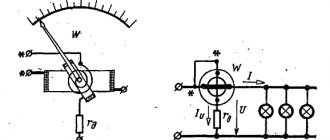
The circuit shown in Figure 1 is a DC voltmeter. To make it variable or, as experts say, pulsating, it is necessary to install a rectifier in the design, with the help of which the direct voltage is converted into alternating voltage. In Figure 2, an AC voltmeter is shown schematically.
This scheme works like this:
- when there is a positive half-wave at the left terminal, diode D1 opens, D2 in this case is closed;
- voltage passes through the ammeter to the right terminal;
- when the positive half-wave is at the right end, then D1 closes and no voltage passes through the ammeter.
A resistor Rd must be added to the circuit, the resistance of which is calculated in exactly the same way as the other elements. True, its calculated value is divided by a coefficient equal to 2.5-3. This is the case if a half-wave rectifier is installed in the voltmeter. If a full-wave rectifier is used, then the resistance value is divided by a coefficient: 1.25-1.5. By the way, the diagram of the latter is shown in Figure 3.
How to connect a voltmeter ammeter
Very often, novice radio amateurs ask the same question: - How to connect a universal Chinese voltmeter-ampmeter to a homemade charger or regulated power supply? Lately I have been literally inundated with questions about how to connect, where to connect. Therefore, I decided to write a specially separate article in which I will tell you in detail how and how to connect a Chinese voltmeter-ampmeter to a charger or a homemade regulated power supply.
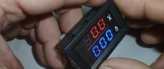
Today, there are two popular Chinese, universal models of voltmeters and ammeters with a built-in shunt, which all beginners and professional radio amateurs, without exception, love to buy in China on AliExpress.
Let's take a closer look at the two models of the most popular voltmeters and ammeters made in China.
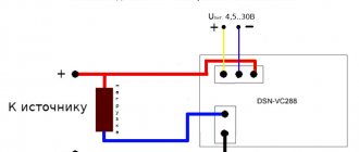
Both devices have five wires for connecting to the power supply. The first one on the left has three thick wires (black, blue, red) and two thin ones (black, red). Thin wires are designed to power the device: red plus, black minus. Thick wires: Black minus ammeter, blue ammeter output, red voltmeter input.
The second device also has five wires, three thin (black, red, yellow) and two thick wires (black, red). Thin wires are designed to power the device: red plus, black minus, yellow voltmeter input. Thick wires: black minus ammeter, red ammeter output.
Every Chinese universal measuring device (UMU) has a built-in measuring shunt for an ammeter, and this is a big plus, because there is no need to “farm” anything, it is done according to the “set it and forget it” principle. In some KUIPs, the shunt is curved like the letter “M” and shiny; I got copies with a copper “P” shaped shunt. As I understand it, the shape and color of the shunt does not affect the quality of measurements in any way.
The devices on the board have tuning SMD resistors with the help of which it is possible to correct the readings of the voltmeter and ammeter.
This figure shows a diagram of connecting a voltmeter-ampmeter of the first model to a charger from a computer power supply.
Connection diagram of a voltmeter, ammeter and fan to a charger from a computer power supply
The device is powered from a separate power source; in this case, it is a five-volt charger from the phone, which can be easily placed in the power supply housing. The fact is that if you connect a voltmeter-ampmeter to the regulated output of the power supply, then when the voltage drops below 4.5V, the device will simply stop working. The fan speed will also decrease, but at low voltage the power supply heatsinks will be a little warm and nothing bad will happen.
When the output voltage is more than 12V, the L7812CV voltage stabilizer comes into operation and thereby maintains a constant voltage on the fan of no more than 12V.
This figure shows a diagram of connecting a voltmeter and ammeter of the second model to a charger from a computer power supply.
Connection diagram of a voltmeter, ammeter and fan to a charger from a computer power supply
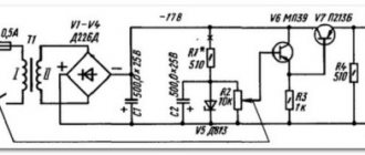
With a charger from a computer power supply, everything is clear. Let's look at the diagram for connecting a Chinese voltmeter-ampmeter of the first model to an adjustable power supply. The top part of the diagram shows a short-circuit protected regulated power supply consisting of a diode bridge, a capacitor, an LM317 voltage regulator, an MJE13009 transistor, a variable resistor and three fixed resistors.
Connection diagram of a voltmeter and ammeter to an adjustable power supply
At the bottom of the circuit, the fan and the Chinese voltmeter-ampmeter are connected through the L7812CV voltage stabilizer to the output of the diode bridge in parallel with capacitor C1. The stabilized voltage on the fan and control unit is no more than 12V.
This figure shows a diagram of connecting a Chinese voltmeter-ampmeter of the second model to an adjustable power supply.
Connection diagram of a voltmeter and ammeter to an adjustable power supply
Many radio amateurs prefer to install analog Chinese measuring instruments (MCIs), which have not lost their popularity over the years, in chargers and regulated power supplies. Therefore, I propose to consider the connection diagram of a classic pointer voltmeter and ammeter.
This figure shows a wiring diagram for a voltmeter and an ammeter with a built-in current measuring shunt.
Connection diagram of a voltmeter and ammeter with a built-in shunt to the power supply
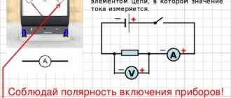
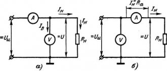
The voltmeter is connected in parallel to the power source, observing polarity. The device should have plus and minus marks. The ammeter is usually connected to the negative wire after the voltmeter. You can also connect the positive wire into the gap; the method of connecting the device does not affect the accuracy of measurements. The main condition is maintaining polarity.
Sometimes there are ammeters without a built-in current-measuring shunt. Then the shunt has to be purchased separately. To avoid additional costs, before purchasing an ammeter, always check with the seller about the presence of a shunt inside the device. Sometimes the cost of a separate shunt is higher than the cost of a device with a built-in shunt.
This figure shows a diagram of connecting a voltmeter and ammeter with a separate current-measuring shunt to the power supply.
Connection diagram of a voltmeter and ammeter with a separate shunt to the power supply
The shunt is always connected in parallel with the ammeter. Without it, the device will simply burn out. How to choose a shunt? If the device is rated at 10A, then the shunt should be 10A. Each shunt has a marking indicating what current it is designed for.
Well, that's all, my article has come to an end, you now have new food for thought.
Friends, I wish you good luck and good mood! See you in new articles!
I recommend watching a video on how to connect a voltmeter and ammeter
How to properly connect a voltmeter
Anyone who does not know, but wants to check the voltage on some part of the electrical network, must ask the question - how to connect a voltmeter? This is actually a serious question, the answer to which lies in a simple requirement - the voltmeter must be connected only in parallel with the load. If a serial connection is made, the device itself will simply fail and you may receive an electric shock.
Read also: What is melting point called?
The thing is that with such a connection the current strength acting on the measuring device itself decreases. At this resistance, it does not change, that is, it remains large. By the way, never confuse a voltmeter with an ammeter. The latter is connected to the circuit in series to reduce the resistance to a minimum.
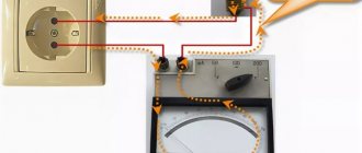
And the last question on the topic is how to use a voltmeter that you made yourself. So, your device has two probes. One is connected to the neutral circuit, the second to the phase. You can also check the voltage through the socket, having previously determined which socket is powered by zero and which by phase. Or connect the device in parallel to the area being measured. The arrow of the measuring block will show the voltage value in the network. This is how they use this homemade measuring device.
We consider simple circuits of digital voltmeter and ammeter, built without the use of microcontrollers on the CA3162, KR514ID2 microcircuits. Typically, a good laboratory power supply has built-in instruments - a voltmeter and an ammeter. A voltmeter allows you to accurately set the output voltage, and an ammeter will show the current through the load.
Old laboratory power supplies had dial indicators, but now they should be digital. Nowadays, radio amateurs most often make such devices based on a microcontroller or ADC chips like KR572PV2, KR572PV5.
Recommended Posts
Since the operation of measuring instruments is affected not only by their own faults, but also by faults in the connected devices, sometimes it is necessary to make adjustments.
The switching was performed when the power supply to the load was turned off.
About the shunt.
Having bought a couple of these ampere-voltmeters, one immediately burned out at 26 volts. No spam, only useful ideas! Connection diagram of a voltmeter-ampmeter and a fan to a charger from a computer power supply. Download a diagram of connecting a voltmeter-ampmeter and a fan to a charger. Everything is clear with a charger from a computer power supply.
In other cases, the display will only show the voltage drop. On the freed contact, on the side of the trimmer, a wire of the desired length is soldered for testing, conveniently mm and preferably red. Solder the SMD resistor Third. Equipped with tuning resistors. For clarity, I recorded the result of my efforts on a video.
Chinese ampere-voltmeter connection diagram
At 10 amps it is already hot. Therefore, I propose to consider the connection diagram of a classic pointer voltmeter and ammeter. By rotating them, you can change the zero values. Circuit YB27VA The device, of course, has its own measurement errors; to adjust the current and voltage readings to those close to reality, two trimming resistors are installed on the board, respectively, one for current and the other for voltage.
In other cases, the display will only show the voltage drop. It is also desirable that the device have a shunt to finalize the connection process. To avoid additional costs, before purchasing an ammeter, always check with the seller about the presence of a shunt inside the device. If you recalculate the divider, then the “preadometer” can be used not only as a voltmeter - for example, you can display current, temperature, etc. It is equipped with tuning resistors.
Lately I have been literally inundated with questions about how to connect, where to connect. I got µV at the input of the op-amp. How to connect a WR device When designing chargers for batteries and various power supplies, many radio amateurs use ready-made voltmeters-ampmeters made in China, which can be easily bought on the Internet, for example, on the Aliexpress website. How to connect a voltmeter ammeter
Chip CA3162E
But there are other microcircuits of similar action. For example, there is a CA3162E microcircuit, which is designed to create an analog value meter with the result displayed on a three-digit digital indicator.
The CA3162E microcircuit is an ADC with a maximum input voltage of 999 mV (with readings “999”) and a logic circuit that provides information about the measurement result in the form of three alternately changing binary-decimal four-bit codes on a parallel output and three outputs for polling the bits of the dynamic circuit indication.
To get a complete device, you need to add a decoder to work on a seven-segment indicator and an assembly of three seven-segment indicators included in the matrix for dynamic display, as well as three control keys.
The type of indicators can be any - LED, fluorescent, gas-discharge, liquid crystal, it all depends on the circuit of the output node on the decoder and keys. It uses LED indication on a display consisting of three seven-segment indicators with common anodes.
The indicators are connected according to a dynamic matrix circuit, that is, all their segment (cathode) pins are connected in parallel. And for interrogation, that is, sequential switching, common anode terminals are used.
↑ File in place...
And now about the modifications that are necessary to bring this “indicator” to fruition.
1. In order for it to start measuring voltage less than 3 Volts, you need to unsolder the jumper resistor R1 and apply a voltage of 5-12V from an external source to its right (according to the diagram) contact pad (higher is possible, but not advisable - the DA1 stabilizer gets very hot).
Apply the minus of the external source to the common wire of the circuit. Apply the measured voltage to the standard wire (which was originally soldered by the Chinese). 2. After modification according to paragraph 1, the range of the measured voltage increases to 99.9V (previously it was limited by the maximum input voltage of the DA1 stabilizer - 30V). The input divider ratio is about 33, which gives us a maximum of 3 volts at the DD1 input at 99.9V at the divider input. I supplied a maximum of 56V - I don’t have any more, nothing burned :-), but the error also increased.
3. If you recalculate the divider, then the “preadometer” can be used not only as a voltmeter - for example, you can display current, temperature, etc.
4. To move or completely turn off the point, you need to unsolder the R13 10 kOhm CHIP resistor, which is located next to the transistor, and instead solder a regular 10 kOhm 0.125 W resistor between the contact pad farthest from the trimming CHIP resistor and the corresponding control segment pin DD1 - 8, 9 or 10. Normally, the dot lights up on the middle digit and the base of the transistor VT1 is connected to the pin via a 10 kOhm CHIP. 9 DD1.
The current consumed by the voltmeter was about 15 mA and varied depending on the number of illuminated segments. After the described modification, all this current will be consumed from an external power source, without loading the measured circuit.
Schematic diagram of a voltmeter
Now closer to the diagram. Figure 1 shows a circuit of a voltmeter that measures voltage from 0 to 100V (0.99.9V). The measured voltage is supplied to pins 11-10 (input) of microcircuit D1 through a divider on resistors R1-R3.
The SZ capacitor eliminates the influence of interference on the measurement result. Resistor R4 is used to set the instrument readings to zero; in the absence of input voltage, and resistor R5 is used to set the measurement limit so that the measurement result corresponds to the real one, that is, we can say that they calibrate the device.
Rice. 1. Schematic diagram of a digital voltmeter up to 100V on SA3162, KR514ID2 microcircuits.
Now about the outputs of the microcircuit. The logical part of the CA3162E is built using TTL logic, and the outputs are also with open collectors. At the outputs “1-2-4-8” a binary decimal code is generated, which changes periodically, providing sequential transmission of data on three digits of the measurement result.
If a TTL decoder is used, such as KR514ID2, then its inputs are directly connected to these inputs of D1. If a CMOS or MOS logic decoder is used, then its inputs will need to be pulled to positive using resistors. This will need to be done, for example, if the K176ID2 or CD4056 decoder is used instead of KR514ID2.
The outputs of the decoder D2 are connected through current-limiting resistors R7-R13 to the segment terminals of the LED indicators H1-NC. The same segment pins of all three indicators are connected together. To poll the indicators, transistor switches VT1-VT3 are used, to the bases of which commands are sent from the outputs H1-NC of the D1 chip.
These conclusions are also made according to an open collector circuit. Active zero, so transistors of the pnp structure are used.
Read also: What glue to glue glass with
How to convert a voltmeter into a DC ammeter
Shunt for ammeter. Or how to make a voltmeter from an ammeter and vice versa.
I decided to write this article when I was making a power supply for my home laboratory. From my own experience, I noticed that the regulated power supply must have a voltmeter to assess the set voltage. And also an ammeter p , for an approximate estimate of the current consumed by the load. It was decided to install these useful elements into the new power source: a voltmeter and an ammeter. After searching in the drawers, I found two suitable measuring heads (the main criterion was the minimum dimensions). With a maximum current of 50µA and 30mA.
First we will make a voltmeter from an ammeter
So, let's move on to the calculations.
The easiest way is to make a voltmeter from an ammeter; I use a second ammeter. For calculations we will need: the maximum current of needle deflection - in my case 30mA, the Maximum voltage that our voltmeter should measure - 30V.
Using Ohm's law we find the resistance: R=U/I, R=1kOhm.
This means that a shunt (resistor) with a resistance of 1 kOhm must be connected in series with the ammeter. In this case we will get a voltmeter. Those. If a current of 30 mA flows through such a series circuit, then the voltage drop across this resistor is 30 V. In my case, I don’t even need to change the scale of the device, just stick the letter “V” to make it clear that this is a voltmeter.
It should be remembered that a current of 0-30mA will always flow through such a voltmeter, depending on the measured voltage from 0-30V. And since it is used in the power supply, this is not critical. We should also not forget that the resistor must be of suitable capacity, which we determine using the formula P = I*I*R, we get P=30mA*30mA*1kOhm=0.9W, we set it with a margin of at least 1W.
It is also necessary to take into account the internal resistance of the device. Then the additional resistor is calculated as follows: Rd=Up/Ii-Ri. Rd is the resistance of the additional resistor; Up — max. the value of the selected voltage measurement limit; Ii is the total deviation current of the selected ammeter; Ri is the internal resistance (of the device frame) of the selected ammeter, it is indicated.
We make an ammeter from an ammeter with a small scale.
The first ammeter has a scale of 50 µA, which is very small, I need 1.5A. To expand the measurement range of the ammeter, you need to install a shunt, but not in series, but in parallel with the measuring head. It turns out that the current will branch and one part will flow through the ammeter, and the other through the resistance. It is necessary to select such a resistance so that a current of 1.5A is divided into two, 50 μA through an ammeter, and the rest of the current through a resistor.
For calculations, you will need to know the resistance of the ammeter, but since I don’t know it, I will make the shunt using the fitting method. To do this, you need to take a copper wire with a diameter of 0.8-1 mm and a length of 1 meter and measure the current at which the arrow deflects to the extreme position.
To do this you will need an adjustable voltage source and load, I used a car light bulb. Next, we adjust the shunt in this way, increasing the length of the wire if we need to reduce the maximum current, or shorten the wire if we need to increase the maximum value of the ammeter scale.
I got this four-layer shunt. I sealed the edges with silicone glue.
It should be remembered that if the shunt accidentally comes off, a large current will flow through the microammeter and it will fail.
An ammeter from a voltmeter is made by analogy with the first option, only the shunt is installed not in series but in parallel. It also happens that voltmeters have internal resistors, which can be removed to create an ammeter.
It should be remembered that the ammeter must have minimal resistance, and the voltmeter must have very high resistance.
Source
Schematic diagram of an ammeter
The ammeter circuit is shown in Figure 2. The circuit is almost the same except for the input. Here, instead of a divider, there is a shunt on a five-watt resistor R2 with a resistance of 0.1 Ot. With such a shunt, the device measures current up to 10A (0.9.99A). Zeroing and calibration, as in the first circuit, is carried out by resistors R4 and R5.
Rice. 2. Schematic diagram of a digital ammeter up to 10A or more on SA3162, KR514ID2 microcircuits.
By choosing other dividers and shunts, you can set other measurement limits, for example, 0. 9.99V, 0. 999mA, 0. 999V, 0. 99.9A, this depends on the output parameters of the laboratory power supply in which these indicators will be installed. Also, based on these circuits, you can make an independent measuring device for measuring voltage and current (desktop multimeter).
It should be taken into account that even using liquid crystal indicators, the device will consume significant current, since the logical part of the CA3162E is built using TTL logic. Therefore, it is unlikely that you will get a good self-powered device. But a car voltmeter (Fig. 4) will turn out to be quite good.
The devices are powered by a constant stabilized voltage of 5V. The power source in which they will be installed must provide for the presence of such a voltage at a current of at least 150mA.
How to connect a voltmeter-ammeter WR-005 100V / 10A.
How to connect a voltmeter-ammeter WR-005 100V / 10A.
How to connect the WR-005 device
When designing chargers for batteries and various power supplies, many radio amateurs use ready-made voltmeters-ammeters made in China, which can be easily bought on the Internet, for example, on the Aliexpress website. Moreover, the cost of such ready-made devices is very attractive, and many suppliers, in addition to everything, provide free delivery of goods to the buyer. Having found the most advantageous offer, we ordered a pair of WR-005 devices for testing, designed to measure voltage up to 100 Volts and current up to 10 Amperes. The order arrived, everything was fine with the blocks, there were no mechanical damages, but there was no passport or instructions describing how to connect the device. This was the reason for writing this article, because, most likely, we are not the only ones who are faced with issues of connecting the WR-005 to measurement circuits.
Similar measuring instruments may be designed for other measurement parameters, but in any case, you will have two connectors on the board:
● The first connector has two thin wires, usually red and black. They serve to supply supply voltage to the measuring circuit. The supply voltage has a very wide range, you can supply from 4 to 30 Volts, the red wire is positive, the black wire is negative. Once power is supplied to the circuit, the indicator will light up. ● The second connector is three-wire, thick wires, intended for connecting the device to measuring circuits. But let's look at the colors of the wires.
Apparently, indicators were previously produced in which thick wires were black, red and yellow, so on the Internet you can find this picture:
In our case, this connector has blue, black and red wires, and the black wire is in the middle of the connector, so we decided to double-check them again.
As it turned out, nothing has changed globally:
● The black wire, as in the previous version, is the common wire (COM); ● Red wire – voltage measurement; ● Blue wire—current measurement.
For those who do not quite understand: the black thick wire is connected to the minus of the source, the red to the plus (the voltmeter will begin to show), the blue thick wire is connected to the load, and from the other end of the load it goes to the plus of the source (the ammeter will show).
About the shunt. In devices up to 10 Amps, the shunt is built-in (soldered directly into the board), over 10 Amps, as a rule, an external shunt should be included in the kit, see the pictures below:
Our version of the device with a built-in shunt:
The external shunt looks like this:
Even after proper connections, there is no guarantee that the voltmeter and ammeter readings will be correct, so it is worth checking them using, for example, an external multimeter. If necessary, you can correct the readings using trimming resistors located on the board of the WR-005 device.
The microcircuit on which the device is assembled does not have any identification marks, but the circuit diagram is like this:
In conclusion, I would like to say that after connecting and testing the device, it showed itself on the positive side, the build quality is not bad, the reading errors correspond to those declared by the supplier, that is, the voltage error is 0.1 Volt, the current error is 0.01 Ampere, current The consumption of the measuring circuit does not exceed 20 mA. Any electronics is subject to failure over time, so how long this voltmeter-ammeter will serve us - time will tell. But, in principle, for the money, we believe that the WR-005 is a worthy purchase with quick installation and connection in devices that require a digital display of current and voltage parameters.
If anyone knows the brand of the microcircuit used in the device circuit, please write in the comments.
Connecting the device
Figure 3 shows a diagram of connecting meters in a laboratory source.
Rice. 3. Connection diagram of meters in a laboratory source.
Fig.4. Homemade automobile voltmeter on microcircuits.
Details
Perhaps the most difficult to obtain are CA3162E microcircuits. Of the analogues, I know only NTE2054. There may be other analogues that I am not aware of.
The rest is much easier. As already said, the output circuit can be made using any decoder and corresponding indicators. For example, if the indicators have a common cathode, then you need to replace KR514ID2 with KR514ID1 (the pinout is the same), and drag the transistors VT1-VTZ down, connecting their collectors to the power supply negative, and the emitters to the common cathodes of the indicators. You can use CMOS logic decoders by connecting their inputs to the power supply positive using resistors.
Setting up
In general, it is quite simple. Let's start with a voltmeter. First, we connect terminals 10 and 11 of D1 to each other, and by adjusting R4 we set the readings to zero. Then, remove the jumper that closes terminals 11-10 and connect a standard device, for example, a multimeter, to the “load” terminals.
By adjusting the voltage at the source output, resistor R5 adjusts the calibration of the device so that its readings coincide with the readings of the multimeter. Next, we set up the ammeter. First, without connecting the load, by adjusting resistor R5 we set its readings to zero. Now you will need a constant resistor with a resistance of 20 O and a power of at least 5W.
We set the voltage on the power supply to 10V and connect this resistor as a load. We adjust R5 so that the ammeter shows 0.50 A.
You can also perform calibration using a standard ammeter, but I found it more convenient to use a resistor, although of course the quality of calibration is greatly influenced by the error in the resistance of the resistor.
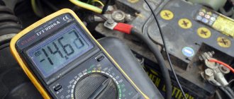
Using the same scheme, you can make a car voltmeter. The circuit of such a device is shown in Figure 4. The circuit differs from that shown in Figure 1 only in the input and power supply circuit. This device is now powered by the measured voltage, that is, it measures the voltage supplied to it as a supply.
The voltage from the vehicle's on-board network through the divider R1-R2-R3 is supplied to the input of the D1 microcircuit. The parameters of this divider are the same as in the circuit in Figure 1, that is, for measurements within 0.99.9V.
But in a car the voltage is rarely more than 18V (more than 14.5V is already a malfunction). And it rarely drops below 6V, unless it drops to zero when completely turned off. Therefore, the device actually operates in the range of 7.16V. The 5V power supply is generated from the same source, using stabilizer A1.
Testing a new circuit
Now, according to the diagram and this photo, we “hang” an addition to the voltmeter: a toggle switch, a fuse and two resistors. The main thing here is to correctly solder the newly installed red and blue wires, however, not only them.
We convert the voltmeter block into an A-meter
But here there are more wires, although everything is simple:
“ payload ” - a pair of connecting wires connects the electric motor “ separate power supply for the voltmeter ” - battery with two more wires “ power supply output ” - a couple more wires
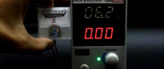
After applying power to the voltmeter, “0.01” was immediately displayed; after applying power to the electric motor, the meter in voltmeter mode showed a voltage at the output of the power supply equal to 7 volts, then switched to ammeter mode. The switching was performed when the power supply to the load was turned off. In the future, instead of a toggle switch, I will install a button without locking, it will be safer for the circuit and more convenient for operation. I was pleased that everything worked on the first try. However, the ammeter readings differed from the multimeter readings by more than 7 times.
Chinese voltmeter - ammeter after modification
Here it turned out that the wirewound resistor, instead of the recommended resistance of 0.08 Ohm, has 0.8 Ohm. I made a mistake in the measurements during its manufacture in the counting of zeros. I got out of the situation like this: the crocodile with the negative wire from the load (both black) moved along a straightened nichrome spiral towards the input from the power supply, the moment when the readings of the multimeter and the now modified ampere-voltmeter coincided and became the moment of truth. The resistance of the involved section of the nichrome wire was 0.21 Ohm (measured with a multimeter attachment at the “2 Ohm” limit). So it didn’t even turn out bad that instead of 0.08 the resistor turned out to be 0.8 Ohm. Here, no matter how you count, according to the formulas, you still have to adjust. For clarity, I recorded the result of my efforts on a video.
