Types of touch switches
Touch switches come in several types:
- capacitive;
- optical-acoustic;
- with control panel;
- with timer.
To make the right choice for your needs, let's look at each type in more detail.
Capacitive
Popular type of switch. The touch sensor is very sensitive, it is triggered when people approach, when the hand is brought to the touch surface or held next to it. Such a switch will be useful in the kitchen because you don’t have to touch it for it to work.
These switches look stylish and are easy to use. They are easier to maintain than conventional key switches.
Optical-acoustic switches
These switches respond to sound or movement occurring within the sensor's range. When there is no one in the room, the light turns off. They allow you to save energy. In apartments, such switches are rarely used. They are often placed in common areas to illuminate rooms or open doors that “sense” a visitor’s approach.
With remote control
Switches with remote control are especially convenient in homes where children or people with disabilities live. They will come in handy if the switch is located inconveniently or is difficult for children to reach. They also provide comfort when you don’t want to get out of bed to turn off the lights or appliances or lower the curtains.
With timer
The timer allows you to turn on and off a device or light in a certain mode. Switches with timers are universal. They are easy to use and work with any type of lamp: LED, halogen or incandescent lamps.
Their advantage is safety. If a short circuit occurs, the switch will automatically move to the off position.
The switches are equipped with indicators that show whether it is currently on. Users also note ease of installation, ease of use, attractive appearance, and reliability.
How to use Wago terminal blocks to connect wires?
A switch with a timer is suitable if you want to regulate how long it runs. This can be convenient when you need to program an electrical appliance to turn on or off. These switches help you save on electricity.
Tools and materials for making backlights
To install a simple automatic lighting system based on an LED strip, you will need the following materials:
- Ice strip.
- Motion Sensor.
- Power unit.
- Controller (when using a three-color RGB version).
- Wires.
- Fastening components.
You will need the following tools:
- Electric drill, screwdriver.
- Measuring device.
- Scissors, screwdriver, knife.
- Soldering iron, solder or connectors.
In addition to the above components, additional equipment and materials may be required depending on the characteristics of a particular backlighting scheme. Let's look at how to choose the main components of the system - LED strip and motion sensor.
How to choose LED strip
There is a large assortment of LED strips, differing in a number of characteristics:
- Color design (monochrome or RGB).
- Shade temperature (warm, cold, natural).
- Dust and moisture protection.
- Power of ice crystals.
- Type of power supply - directly from a 220 V network or through a step-down transformer.
When choosing a tape, you must be guided by the following criteria:
- The most common model of ice strips is equipped with SMD LEDs with a crystal size of 3528. Their lighting parameters are similar to a natural source.
- SMD 5050 LED strips have maximum brightness.
- The stronger and more uniform the backlight is required, the greater the number of diodes should be located per meter.
- Lamps installed near a source of high humidity (in the kitchen, in the bathroom, near the floor surface) must have a high IP protection index - from 67-68.
Note! Based on the type of power source, LED strips are divided into those powered from a 220V network and from a power supply, usually 12V. The latter is used for ice strips no longer than 5 meters and is calculated based on the total power of all diode elements. The backlight on such a device will be somewhat more expensive and more complex than in the case of the first version of the tape.
How to choose a motion sensor
According to the main principle of operation, the motion sensor is similar to a regular switch. Only the closure of the contacts in it occurs automatically - under the influence of the sensor, and not by a human hand. Depending on the type of mechanism, they differ into the following modifications:
- Infrared.
- Ultrasonic.
- Acoustic.
- Optical.
- Microwave.
The choice of a specific model depends on the operating conditions and the tasks assigned to the lighting system. For example, in normal everyday conditions, conventional infrared sensors are used to illuminate stair steps, the operating principle of which is based on determining the thermal radiation of an object.
Among the main operating parameters of the motion sensor are:
- Light level when the sensor starts to respond.
- Glow time after switching on.
- Backlight brightness control.
- Viewing angle.
- Sensitivity, range.
Advice! To prevent the LED strip from turning on when the room is light from natural light, it is necessary to install a sensor with a photo relay. Thanks to it, the device will start working only after a certain degree of darkness.
Setting up the control panel
Touch switches look really very stylish - they will look great in the living room, in the hallway, in the kitchen, and anywhere. Another good thing about such devices is that they can be controlled remotely. To do this, you just need to order a universal remote control online. The price of this device, which is a keychain with a carabiner and a metal front panel, is not so high.
There are four buttons on the remote control panel, they are designated in Latin letters - A, B, C, D. This device operates on a 27A battery with a voltage of 12 volts. This remote control is compatible with a variety of touch switches, in particular, with the popular LIVOLO switches of the C6 and C7 series.
Setting up this remote control is quite simple. First of all, you need to press the touch switch button (while it itself must be in the “off” position) and hold it until the “Pi” sound signal is heard from the touch device - this is about 5 seconds.
Then you should press one of the buttons on the remote control (A, B or C), as a result of which another sound signal should be heard - it means that the “binding” procedure is completed. Now the button that we pressed on the remote control during binding can be controlled (disabled, enabled) by touch switches at a distance. All other buttons on the switches are linked to the remote control in exactly the same way.
It is worth noting that several touch devices can be assigned to one button on the remote control. That is, several buttons and even several remote controls can be linked to one sensor. There is information on the Internet that you can make 8 such bindings (I haven’t tried it myself).
| At the same time, button D has a slightly different function than all the others - it is designed to turn off all three lines at once. |
Detaching the sensor from the remote control is also very simple. To do this, touch the sensor and do not release it for about ten seconds
After five seconds the first beep will sound, but this should not be taken into account. And only when another, second beep is heard, all previous settings will be reset
The operating range of the VL-RMT-02 universal control panel is 30 meters. This is quite enough for everyday use - the remote control will properly perform its functions throughout the entire territory of an ordinary apartment.
Connecting a single-key touch switch Livolo VL-C701R
So, let's figure out how to connect a 220 Volt touch light switch. In essence, it is no different from the connection diagram of a single-key switch.
On the switch body there are two terminals marked “L-in” and “L-load”. The “L-in” terminal, the literal abbreviation of which sounds like “live line terminal”. If we use electrical engineering translation, it means approximately the following: “live line” - live line, “terminal” - contact, contact screw. In general, this is a contact for connecting the PHASE wire (the one that came from the distribution box).
The “L-load” terminal in the instruction manual is called “lightin terminal”, translated approximately like this: “lightin” - lighting devices, “load” - load. That is, this is a contact for connecting the wire that goes to the lighting load (the wire that goes to the lamp or chandelier).
As you can see, there is nothing complicated in this “electronic miracle”, everything is like in a regular switch, two terminals “phase-input”, “phase-output”. We strip the wires to the required length and connect them to the terminals.
If you are installing a touch switch to replace the old one, simply unscrew the wires from the old one and connect it to the new one. The main thing is to decide where the phase is and connect it to the desired contact of the touch light switch ("L-in" contact).
The only thing I would recommend is that if you use a cable with a stranded core, use NShVI lugs. The touch switch has screw-type terminals, and if you push a bare stranded wire there when tightening, you can easily crush it.
This is what the Livolo switch looks like from the side
Switch with on indicator
Switches with indicators differ from LED switches in a completely different principle of use - the lamp in them lights up when the lighting is turned on. The main purpose of a pilot light is to signal that lights are on in a basement, attic, storage room or outdoors.
Used to control energy consumption. The indicator can be set for each of the keys or only for one of them.
The connection and operation diagram of a switch with a backlight function is built according to the following principle. The test lamp is connected in parallel to the switch terminals. When the circuit is completed, current flows through the indicator and the light fixture - both light up. If the switch is off, no current flows to either the indicator or the lamp.
Indication of switched-on lighting can be done in combination: 1 indicator lamp per key or one lamp for each key (+)
Scheme for connecting an LED to a switch in an apartment
Diagram and appearance of the switch
As you can see, the device consists of only two elements - a current-limiting resistor and a light source.
Many people who are not related to radio electronics may be confused by this scheme. After all, we put the LED in a 220V AC switch, although the LED itself is designed for a voltage of 2-12V DC. And the main lamp, in theory, should also glow with this connection.
How and why does it work?
Let's remember the school physics course:
- Voltage is the potential difference at the two ends of a conductor. The higher the voltage, the faster electrons travel through the wires.
- Current strength is the density of electrons in a conductor. When an electrical circuit encounters a section with high resistance along the path of electrons, some of them give up their energy to this section.
When the current (electron flux density) is significantly greater than the area can handle, the excess energy is converted into heat. If there were no resistor in front of the diode, the current passing through it would be many times greater than its rated parameters, turning the diode crystal into a cloud. In this circuit, the resistor acts as a valve, cutting off most of the current. Current will also flow through the incandescent lamp itself, but its strength is so small that the coil will not heat up.
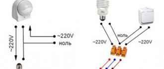
Light sensor connection diagram.
It is much cheaper to buy a motion sensor separately and connect them to a spotlight or lamp, and in addition, this significantly expands your choice, because there is a rather limited choice of models with a built-in sensor.
And connecting a motion sensor with your own hands will be as easy as a regular switch. Both have the same principle of operation - opening and closing an electrical circuit, but simple - you need to press for this, and the motion sensor does this automatically when necessary.
The most common scheme is when a 220 V electric power cable and a lamp are inserted into the sensor housing. The incoming phase goes to L, zero goes to N from the same terminal, if a second N is not provided, zero goes to the lamp. The phase controlled by the sensor also leaves the third contact for the second contact of the lamp.
Connections are made in the same way when using an intermediate junction box.
It is quite rare that under certain conditions it is necessary for the lamp to work constantly, bypassing the sensor by turning on the most ordinary switch. To do this, as shown in the second diagram, the phase from the lamp must bypass the sensor and go to the switch, and through it connect to the phase of the electrical network of your home.
To constantly turn on the light, you need to close the contacts of the switch, and if you open them, then the lighting will be controlled by a motion sensor.
Battery powered
This connection option allows you not to use electricity, which is convenient in some circumstances. Powering the LED device from batteries is possible if you plan to connect a short section with low power for short-term use. In this way, you can connect duralight, for example, to illuminate shelves, pictures or a work surface in the kitchen.
Any batteries will do; their total voltage should be from 8 to 12 V.
The work order is as follows.
- Strip the contacts on the batteries, tin the ends of the wires and solder them to the plus and minus of the battery, respectively.
- When connecting the toggle switch, the plus from the battery is connected to its input, and the output is connected to the minus of the duralight.
- Solder the free ends of the contacts to the tape, remembering the polarity.
LED strip connected to a battery.
Comparison of self-assembly and boxed solution
On the market you can find a huge number of different lighting systems based on LED strips with motion sensors. However, self-production has the following advantages over them:
- The ability to accurately assemble a device in terms of length, dimensions, brightness, power, number of sensors in accordance with operating conditions. For example, it is difficult to select them for stair steps in terms of length and number of sensors.
- The price will always be lower than factory analogues. You can put inexpensive components into a homemade circuit that are not much inferior in quality to versions from the store. At the same time, in factory models only a ready-made branded set is provided.
- No warranty. Although this point can be neglected when using high-quality components, the device will work for many years in trouble-free mode.
Purchasing ready-made factory backlight models based on LED strips with motion sensors also has its advantages:
- The ready-made kit does not require searching and selecting various components, including fasteners and wiring.
- Warranty and service from the manufacturer.
- Possibility to order turnkey installation.
Making automatic lighting based on LED strips with motion sensors or buying ready-made solutions is everyone’s choice. You need to take into account your capabilities, strength, experience in carrying out such work and the availability of high-quality and inexpensive components.
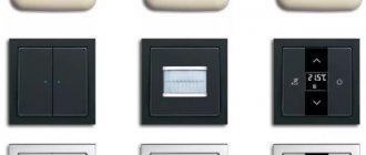
Types of switches with a sensitive element
LED backlighting differs from other lamps in its low power consumption (up to 24 V), so the rows of diodes are connected to the network through a power supply. The choice of the latter should be made with a power reserve of 15–20%. The switch is located between them.
Ribbons with single, single-color crystals can be used with a regular button. Complete with color LED rows, RBG controllers are used. The touch switch for the LED strip does not require mechanical force to close the circuit and has a number of advantages:
- non-contact operation allows you to avoid contamination with grease in the kitchen, machine oil in the garage, paints and other things in the workshop;
- prevents moisture from entering the mechanism;
- in medical institutions, reduces the doctor’s contact with potentially contaminated surfaces;
- equipped with additional functionality;
- the appearance is laconic, placed in an aluminum profile along with an array of diodes.
Touch switches for LED strips are boards that fit into an LED profile (average dimensions 40*10*2 mm), external modules in a plastic case or controllers with a remote control. Depending on the length and power of the belt, models with corresponding characteristics are selected:
- incoming and outgoing voltage;
- standby and load current;
- power.
For monochrome LED strips, 2 types of switches that differ in operating principle are used. In capacitive devices, the spring fits tightly to the plate and provokes vibration when touched, creates contact and turns on the light. If the diffuser is made of plexiglass with a thickness of more than 1 mm, the mechanism will not work. The infrared receiver responds to the reflection of a signal from an object within the range of the optical sensor (up to 100 mm). If the distance between the sensing element and the protective screen is more than 5 mm, a hole in the light-diffusing lens or a profile of a shallower depth will be required.
Touch dimmers adjust lighting brightness from 10% to 100%. A short touch (approaching your hand) turns the lighting on and off, and a long touch changes the brightness. The operating principle may be different: each interaction switches a pre-programmed lighting scenario. The control panel for RBG strips (LEDs made of 3 crystals of different colors) is supplemented with a touch ring. The device is simple and understandable. As you move your finger along the spectral circle, the hue of the glow changes. In this case, the adaptation mechanism uses diodes of a certain color separately or in combinations. The simultaneous operation of all crystals produces cool white lighting.
- an adaptive indicator reacts to the level of illumination in the room, automates the operation of the lamp depending on the time of day, penetration of sunlight and the presence of other sources;
- protection against short circuits and polarity reversal;
- motion sensor (range 3-5 m, coverage angle
100%);
timer; “guided light” - gradual fading, so as not to get out of the room in the dark.
Motion sensors
A device such as a motion sensor is used to turn on or off, mainly a lighting device, by switching the supply voltage to electrical devices installed in pairs with it. It is triggered as soon as a disturbance occurs and is applied to its sensitive element.
Let's take an example of an infrared motion sensor, the operating principle of which is based on monitoring an increase or decrease in the level of IR radiation. And to capture human movements in space, the device uses Fresnel lenses. Such a lens captures infrared radiation and focuses it on a pyroelectric element, which generates a certain number of pulses, the number of which depends on the intensity of a person’s movement. When pulses are continuously supplied to the pyroelectric element, the motion sensor switches the electrical signal to the power supply and the LED strip is activated. When a person stops moving, and accordingly stops changing the level of infrared radiation focused by the lens, it stops working and the LEDs go out.
Quality or price?
Based on the basic principles of operation of touch-type switches, analogues that are not the best in their characteristics are often manufactured. Therefore, you should not save when choosing - quality is always a priority. The price of the product is determined by its technical parameters. A universal device has a high cost.
Touch switches, which are of good quality and functionality, are imported from abroad and are more expensive. Domestic products have a lower price, but their parameters are far from ideal.
Preference should be given to manufacturers with extensive experience in developing exemplary products
They protect their reputation, which means it is important for them to ensure proper quality control during the production process.
Are touch switches a priority? In fact, this is a progressive step in the development of lighting control elements. Just as previously rotary models are a thing of the past, semiconductor sensitive devices will replace mechanical switches. And consumer demand will increase when prices for these products stabilize.
Lamp selection
The LED strip will be chosen correctly if you take into account its technical parameters and the characteristics of the room. When choosing a lamp, it is recommended to pay attention to the following characteristics:
- Radius of the device. The main parameter when selecting a location for mounting the sensor.
- Light source power. The characteristic is important because it determines the brightness and quality of the light.
- Viewing angle. The maximum viewing angle is 120 degrees, which must be taken into account when placing the sensor.
- Manufacturer's declared service life.
- Reputation of the manufacturing company.
- The efficiency of light, determined by the illuminance factor. The indicator depends on the power of the device and the number of light diodes on the tape.
- Tape length. The indicator is important when choosing an adapter that supplies power to the light source. Recommended ratio: per 1 meter of length - 800 mA. If the adapter gets too hot, you will need a more powerful device.
DIY dimmer
We have more or less figured out the dimmers for the LED strip. The time has come to find out how to make a dimmer with your own hands, and whether it is even possible. Since I don’t know your level of preparation, I’ll focus on a fairly simple scheme. It is made on an accessible element base, but performs the functions of a dimmer quite well and will fit into the body of a standard switch.
A classic multivibrator with variable duty cycle is assembled on transistors VT1, VT3, and the right arm of the multivibrator is reinforced by transistor VT2, which forms a push-pull switch with VT3. The capacitances of capacitors C2 and C3 are selected such that at any duty cycle the generator frequency is 14 kHz
This will eliminate flickering of the tape and its “ringing” at low brightness. The duty cycle is changed using variable resistor R3.
The multivibrator is loaded onto a powerful switch made of field-effect (MOSFET) transistors VT4, VT5 connected in parallel. Diode VD1 protects the transistors from reverse induction voltage, which can occur in the SL supply wires if they are long enough.
The circuit uses field-effect transistors with an N-type channel. What if you find similar ones with a P-type channel? It's OK. There is no need to change the dimmer circuit itself, just swap the extreme terminals of the variable resistor R3 and change the connection circuit of VT4, VT5.
This device allows you to adjust the brightness of the tape from 10 to 90%, which is not bad for such a simple scheme.
Now for the details. KT315 and KT361 are the most common transistors among radio amateurs, and they can be found in almost any domestically produced household equipment of the 90s. Even now in the KeTeshki store they cost a couple of rubles.
Field-effect transistors can be removed from any motherboard of a faulty PC. If the SL power does not exceed 35 W, then transistors VT4, VT5 can operate without a radiator. If the power is higher, then a radiator will, of course, be needed.
Main conclusions
Anyone can make a backlight from an LED strip with a motion sensor. For this you will need:
- Ice strip, power supply, controller.
- Motion Sensor.
- Wiring.
- Installation tools (drill, screwdriver, screwdriver, soldering iron).
Before starting installation work, you need to correctly select both the LED strip itself, the transformer for it, and the motion sensor in accordance with the operating conditions. When connecting, you must follow the instructions and observe safety precautions for electrical installation work. Whether to make such a lighting system with your own hands or buy it in a store depends on many factors, including experience, availability of materials and complexity of the design.
If you have your own option for connecting and using an LED strip with a motion sensor, be sure to write about it in the comments.
DIY touch switch
Considering a touch switch in terms of self-production, I would like to deviate a little from the numerous diagrams presented on the Internet and make it more unified. A simple switching system is relatively uninteresting and poorly applicable in everyday life. There are many reasons for this, but one of them is the sensitivity of simple designs to the characteristics of the power supply network and the constant occurrence of false alarms due to other electrical appliances. In addition, I really wanted the circuit to be used instead of a classic switch, but with the addition of the ability to adjust the brightness of the light. That is, with peculiar dimmer functions. At the same time, it is extremely undesirable to overcomplicate the structure of the circuit.
As a result, the following design was chosen:
The device is connected to the load power line break through contacts F and 0. The built-in LED indicator D1 notifies about the current operating mode. Three contact sensor pads are used, which can be any conductor from 3 cm². One gives a signal to turn on the device, the other two regulate the brightness of the light. The control part is the AT90S2313 microcontroller, which can be easily replaced with an ATtiny2313.
General list of circuit elements:
| Marking | Denomination | Note | Analogs |
| Capacitors | |||
| c8 | 0.33 µF, 400 V | ||
| s7 | 0.1 µF, 630 V | ||
| c6 | 100 µF, 6.3 V | Electrolytic | |
| c4 | 0.1 µF | ||
| C1, 5, 9, 10 | 100 pF | ||
| Diodes, zener diodes | |||
| D1 | |||
| D2 | diode | ||
| D3 | 6.2 V | zener diode | |
| Resistors | |||
| R1 | 330 Ohm | ||
| R2, 7 | 1.2 MOhm | ||
| R3 | 1 MOhm | ||
| R4 | 3 MOhm | ||
| R5 | 430 Ohm, 1 W | ||
| R6 | 1.5 MOhm | ||
| U1 | AT90S2313 | ATtiny2313 | |
| Q1 | BT138-800 | semistor | BTB12-800, Q8015R5 |
| X1 | 4 MHz | Quartz resonator | |
| F1 | 3.5A | fuse |
What are dimmers
Touch switches with a dimmer allow you to change the level of lighting in the room. Conventional devices operate in two modes - on/off. Dimmer allows you to adjust the brightness of the light on your Device.
taste with such a device is important thanks to:
The advantages of being able to change the brightness help reduce energy consumption. The indicator decreases by 50%. opportunity Allows you to adjust the lighting to the situation. in the evening, For example, after a busy day at work, you can reduce the brightness to twilight
If there are several switches in the room, using a dimmer you can focus attention on one part of the interior
Advantages of touch switches
The advantages of touch switches include:
- increasing the service life of electricity consumers (due to the possibility of smooth switching on, which eliminates even short-term operation in extreme starting mode),
- long service life,
- reliability,
- compatibility with any lighting devices (incandescent lamps and other types of lamps),
- Possibility of economical operation of consumers and power regulation.
In order for the touch lamp to live up to expectations and significantly increase the comfort of the room, it is important when choosing to take into account all your needs and determine what functions you would like to “entrust” to the device. It will be easier to formulate requirements if you answer the following questions:
- How many light sources are you planning to connect to the touch switch?
- Where are you planning to install the switch (do you need a model that is resistant to temperature changes or )?
- Are there plans to connect additional electrical appliances, and is it necessary to automatically control their operation (presence of a temperature sensor)?
- Do you need a function to automatically turn on the lights when people appear in the room and turn them off when they are absent (motion sensor)?
Legrand
Multi-brand company with a central office in France. In Russia there is not only a representative office of the company, but also a production site, however, in Dubna, where it is located, they produce only small-section cable channels. Touch switches, distinguished by good quality and functionality, are imported from abroad and have a real “imported” price: a single-channel device costs about 3.5 thousand rubles.
Livolo
Domestic products are traditionally competitive in terms of prices, however, their characteristics often leave much to be desired. The products of the Ekaterinburg company Livolo cannot be called of poor quality, however, its touch switches may not work correctly with LEDs (lamps, strips) etc. But the price of a three-channel device is less than that of a single-channel imported device - 2.1-2.3 thousand rubles.
Technologies do not stand still, and now we already have a touch switch in wide use, which allows us to take the lighting control system in the house to a fundamentally new level.
Our article will tell you why such a device is needed, what it is and how it works. Thanks to this, you can make a touch switch with your own hands for 12 or 220 volts without any problems, and the connection itself, both a home-made device and a purchased one, will not be difficult.
Advantages
One of the main qualities of LED light sources is their long service life. The lamps can last for many years (30 – 50 thousand hours).
Another advantage of diodes is efficiency. For example, a meter strip with 60 LEDs needs 5 W of power. As a result, monthly consumption for the tape will not exceed 1.2 kW/h. It is estimated that using tape can save up to 90% of energy.
Other advantages of LED strips:
- No flicker. Thanks to this quality, LEDs do not overload human vision with their light.
- Ease of use. Tapes are placed in any desired location.
- No overheating. LEDs are not prone to excessive heating, which allows them to be installed on surfaces made of almost any material.
- Light weight.
- Ease of Management.
- Reliability of the design. The tape is strong enough to withstand mechanical stress.
- Easy installation. This makes LED strips radically different from all other lighting devices. Anyone - even someone ignorant of electrical engineering - can install the tape.
When choosing a tape, you should keep in mind the purpose of the purchase. There are several types of LED lighting, differing in technical characteristics:
- street;
- internal;
- peripheral.
Through-action switches
The convenience and practicality of this type of device are obvious. Electrical networks equipped with such communicators are operated more efficiently, since in the end there are actual energy savings.
For example, to cross a long corridor, the lighting is turned on at the entrance and turned off at the exit. This function is implemented by just two devices mounted at different ends of the corridor.
If we compare the design with a conventional on/off device, the difference is noted in the number of working contacts of the devices. The design of a simple switch provides only the closing/opening of two contacts.
The wiring of the pass-through switch involves the creation of three working lines, of which one is common, and the other two are changeover lines. This makes it possible to control a section of an electrical circuit from various points.
Operating principle of the single-key model
Actually, the principle of the function looks simple and clear. The changeover contacts existing in the structure in the first position close one segment of the circuit and open the other, and in the second position of the changeover contacts the circuit is inverted.
On the body of each branded switch there is always a schematic diagram of its connection. For example, the user has a single-key device at his disposal. It is necessary to include it in a simple control circuit for one lamp.
If we refer to the installation diagram of a single-key pass-through switch, which is contained on its body, the user’s actions boil down to the following:
- The first (C) contact is connected to a common line.
- Changeover segments are connected to the second (P) and third (P) contacts.
- Install two devices at previously designated points.
The changeover contacts (P) of the two switches, identical in number, are connected to one another by conductors. The first (common - Common) contacts of the two devices are connected - one with the phase wire, the second with the “zero” wire through the lamp lamp.
The operation of the circuit is tested as follows:
- The mounted section of the circuit is provided with voltage.
- Switch the key of the first switch to the “On” mode.
- The lighting lamp lights up.
- Follow to the location of the second device.
- Change the current position of the key of the second device.
- The lighting lamp turns off.
Now, if you do all the operations in reverse order, the effect of the lighting system will be similar. This confirms the normal operation of the circuit.
How to do the actual installation
Before you begin installing an apartment (or other) walk-through switch, it is recommended to draw a wiring diagram, something like this:
The current supply to the section of the circuit with pass-through switches is usually carried out through a standard distribution box. Thus, the first step of installation is selecting the optimal location for the junction box, installing it and supplying electrical wiring. The three-core cable (phase-zero-ground) is brought into the box.
In addition to installing the distribution box, the natural need remains to prepare niches for mounting the chassis of walk-through switches. The most convenient places are also chosen for them. Typically, devices are mounted next to the frames of pass-through doors.
Having completed the preparatory installation procedures, proceed to connecting the separated conductor lines. The first is connected to any of the switches, to its 1 output (phase conductor).
Next, the conductors are connected between the changeover contacts. The last line to be connected is the zero line to the remaining free first contact of the second switch. All that remains is to supply voltage to the assembled circuit (turn on the circuit breaker) and test the assembly for correct operation.
Cross designs
There is a modification of the devices - cross switches. Structurally, they are devices with four contact switching. Their main purpose is to help design switching circuits for lamps and other devices from three or more control points.
Meanwhile, to implement such circuits involving cross models in the structure, it is necessary to use conventional pass-through switches. The circuit implementation involves the inclusion of cross modifications in series between a pair of conventional pass-through switches. The crossover model has a pair of input terminals and a pair of output terminals.
Products are produced for external (surface) installation and devices for use in hidden wiring networks. There is a wide choice of load capacities, and the variety of colors and designs also does not limit user needs.
Tape selection
Having determined the installation location, select the light strip itself. At its core, it is a set of LEDs interconnected and located on a long plastic surface. The consumption of the entire strip and its elements is calculated for a certain power, which is indicated on its packaging. The usual power supply parameters are 12 or 220 V. The latter are basically a variation of the former, only they are equipped with the included conversion unit. Accordingly, if it is not there, you will have to additionally resolve the issue with energy supply. In this case, in addition to the transformer, you can use a battery assembly with recharging, connecting it to the power supply of the LED strip. In addition to those listed, a 24 V tape is occasionally found. You will also have to purchase a separate power supply for it.
The main characteristic is always the brightness of the light strip. It directly depends on the number of diodes per meter and their type. The most widely used semiconductor elements are labeled SMD 2825, 3528, 5050, 5730 and 5060. The difference between them is only in brightness, which means they are required less per 1 m of LED strip. The average number of elements of such a segment ranges from 30 to 60 pieces. Accordingly, the consumption of each meter can reach 14.4 W, which must be taken into account when choosing the characteristics of the power supply.
The average length of LED strips on trading floors ranges from 0.5 m to 100 m. The strip can be divided by connecting the contacts of each part to the power supply. The only limitation is the places where the line can be connected. They are indicated on the tape with stripes, dotted lines or special marks. This is due to the design of the LED strip. Typically, the internal circuit of the strip consists of many links, each of which is several series-connected LEDs (usually three) with a current-limiting resistor. Each such block is connected in parallel to the next one in the tape. The cut can only be made at the junction of one chain link to another.
The color produced by the diodes can be any, including options with a variable spectrum using a manual regulator. The most common primary colors are red, yellow, white, blue and green. When used indoors, with a motion sensor for an LED strip, the white or yellow emission spectrum is most suitable.
The choice of power supply system depends on the availability of a public network connection. If the place is too inconvenient for pulling power wires, then a battery-powered LED strip with a motion sensor can be used. In such cases, the sensor is often already included and is located on the body of the unit in which the batteries are located.
Installation
When carrying out installation work, it is necessary to take into account the location of the sensor. This is necessary for the device to effectively detect moving objects. The figure below shows the correct placement of the sensor on a rectangular wall. The red lines indicate the human detection zone.
A standard sensor detects the location of an object at a distance of 6 – 15 meters. This distance is enough to detect a person in small and medium-sized rooms. In large rooms, chains of sensors are used that work in conjunction with each other.
Connecting the diode strip to the sensor is not difficult. The sensor is equipped with terminal clamps built into the device body. The terminals are connected to conductors that go to the power supply of the LED strip. In the power supply, the voltage of 220 V is transformed into the required voltage according to technical regulations (12 or 24 V).
Connecting an LED strip to an infrared motion sensor is a fairly simple task that can be completed by anyone who knows the basics of electricity and electrical engineering.
The figure above shows the simplest connection diagram to an LED strip. Legend:
- L - phase (220 V);
- N - zero;
- black wire is the switched voltage path from the sensor to the diode strip.